


 42 / 116

42 E L EC TR I C AL CONNEC T I ON
AU T UMN 20 1 7
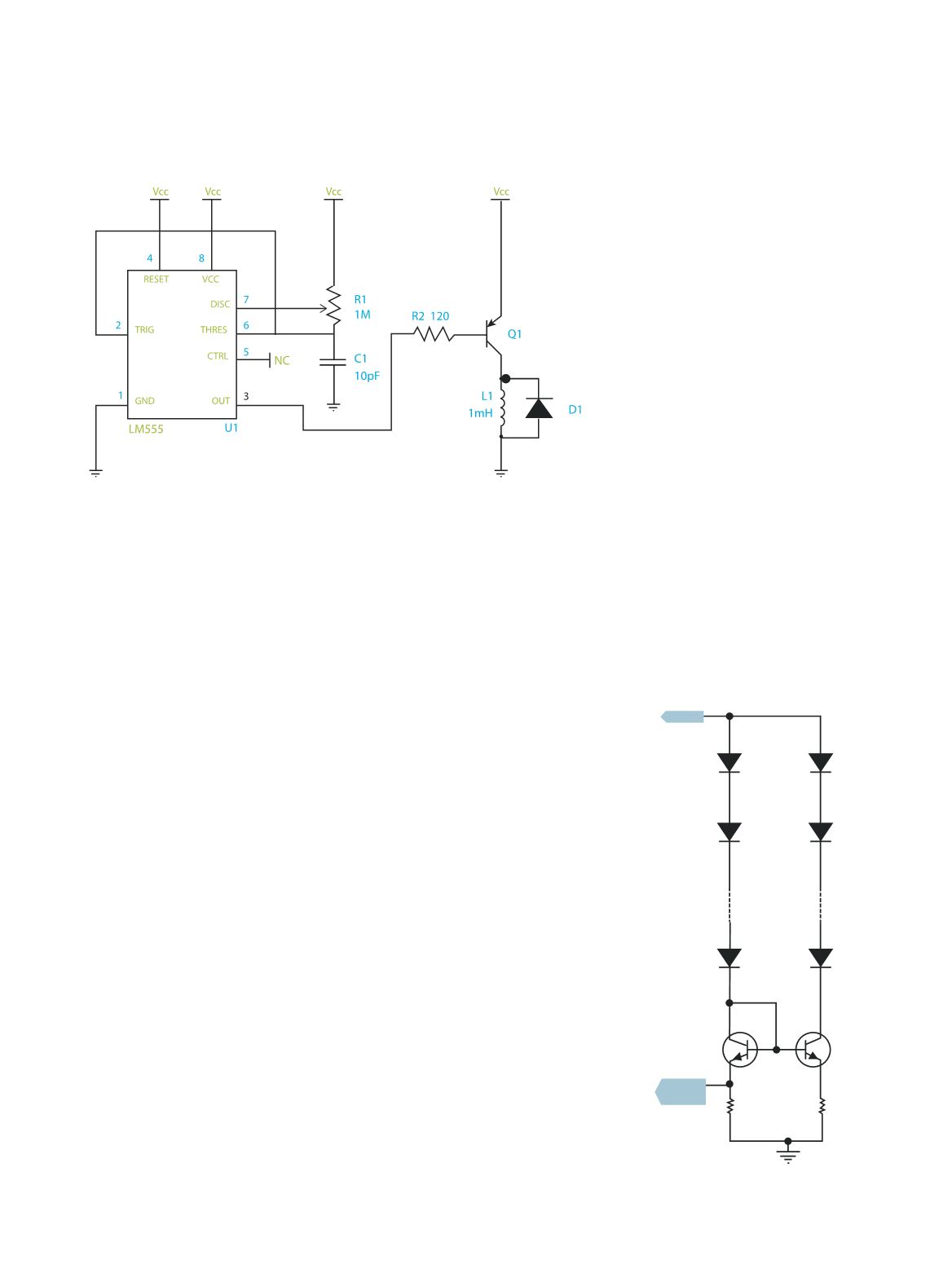
output of pin 3 of the LM555 is low,
transistor Q1 turns on and the inductor
L1 stores magnetic energy while the
LED conducts current. When pin 3 goes
high, Q1 switches off but the LED is still
being supplied with current via the L1
stored magnetic field.
Providing constant current is one
thing; splitting current equally among
several LED strings connected in
parallel is another, and it becomes
important in large luminaires.
That task can be achieved by current
mirrors. A current mirror is a circuit
block that functions to replicate the
current of a particular active device in
another active device. An important
feature of the current mirror is a
relatively high output resistance,
which helps to keep the output current
constant regardless of load conditions.
Another feature of the current mirror
is a relatively low input resistance,
which helps to keep the input current
constant regardless of drive conditions.
A current mirror is shown in Figure 7.
The sense resistor RS1 in the left-hand
LED string sends a feedback voltage
to the current regulator (not shown)
feeding both strings.
Transistors Q1 and Q2 are identical
types and ideally should be mounted
on a common heat sink so that their
thermal characteristics are matched.
Transistor Q1 with its collector
connected to the base is turned on
hard and supports only a small voltage
difference between emitter and
collector. Q2 is basically an emitter-
follower circuit, that is, it replicates the
base to ground voltage on the sense
resistor RS2.
Therefore RS2 will be equal to RS1
in value or adjusted to be very close
in value. In this way both strings draw
equal current. Further strings can be
added, and appropriate transistors
must be chosen for that task.
Although it is simple circuitry,
several disadvantages can arise.
One is that matched transistor pairs
are generally limited in power (thus
limiting string current).
Another is that larger differences in
total forward voltage in strings can also
limit current. If, for example, the left-
hand string has a larger voltage drop,
the difference shows up in a larger
collector to emitter voltage drop on Q2,
thus limiting current in that string.
A more flexible form of individual
string current control is shown in
Figure 8.
In this circuit the two strings have the
same supply voltage, as in the current
mirror example. This voltage can be set
at a level appropriate to the largest of
forward drops likely to occur – and even
to allow for a bit of extra ‘headroom’.
The field effect transistors (FETs)
(Q1 and Q2) can be thought of as
trimming resistors. The operational
(high gain) amplifiers feed the base
regions of the FETs. By eliminating
the difference signal (connected to
the negative input), the voltage drop
– and therefore the current – is kept
constant on the sense resistors.
IS DC THE EFFICIENT SOLUTION?
The short answer at present is no, but
there are some important qualifiers.
The first is that there isn’t a range of
commercially available DC-DC power
supplies for LED lighting. What we have
is a plethora of drivers, all of them with
AC input.
Typically the spread of power ratings
Figure 6: The switch mode form of current regulator.
Vin
Q1
Rs1
Reference
Voltage
Q2
Rs2
Figure 7: A current mirror.