


 40 / 116

40 E L EC TR I C AL CONNEC T I ON
AU T UMN 20 1 7
DC power supplies are the preferred
solution. At a typical forward voltage of
3.3V, a string of eight LEDs requires in
excess of 26V.
For lower voltages, fewer LEDs
can be incorporated, or parallel
connections must be employed. The
latter topology can exhibit problems
with unequal current division, as
there will always be some
differentiation between individual
LED forward bias characteristics.
Variation in forward voltage can
be about 20%, so significant voltage
differences can occur on series strings.
To ease the difficulty of paralleling
strings, LED manufacturers make use
of fairly elaborate binning procedures.
The aim is to match LEDs on the basis of
forward voltage and also for current-
luminous flux and spectral distribution.
In many embodiments of luminaires
for commercial and industrial use,
reliance is placed on LED drivers for
correct biasing, rather than on the
selection of matching components.
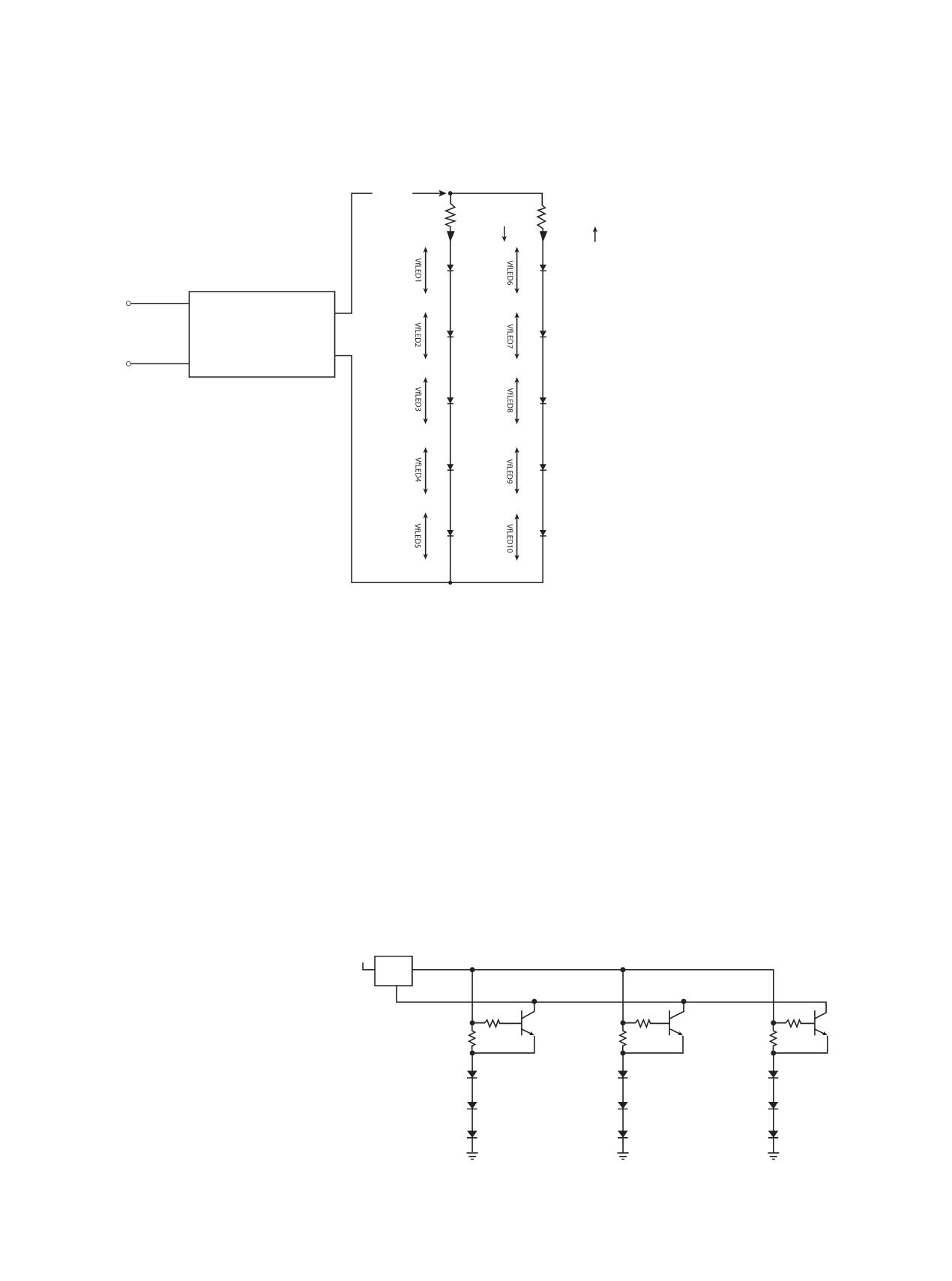
In larger power luminaires, a
combination of parallel string clusters
is employed (Figure 4). For these
arrangements care must be taken to
provide current balance in the
strings. Ideally, current balance is
provided through the use of constant
current sources.
The simplest arrangement for a
constant current source is the use of
a high-value resistor, but a relatively
high voltage is then required. In
practice a constant current source
relying on feedback is the best solution.
To achieve this a power supply with
feedback is employed, as shown in
Figure 5.
The current regulator requires a
constant voltage on the sense rail so
that all three LED strings draw the
same current. Should an LED open in
one of the strings, excess current in
the remaining ones should be avoided.
This is achieved by using switching
transistors Q1, Q2 and Q3, each with its
own sense resistor.
If an LED fed by Q3 opens, the base
and emitter of that transistor are
‘commoned’, opening up the collector.
Note: the LM317 is a popular Texas
Instrument product. However, such
linear current regulators have low
efficiency, thus negatively influencing
what is gained from the high inherent
efficiency of LED luminaires.
The switch mode form of current
regulator is not only more efficient
but also provides for basic dimming
capability. The basic circuitry is shown
in Figure 6.
The LM555 is a Fairchild device
for generating accurate time delays
and oscillating waveforms. In the
illustrated circuit the device is used as
an oscillator, generating a square wave
in conjunction with R1 and C1.
R1 is a potentiometer and allows
the frequency to be varied. When the
2222
R6
LED7
MPS2222
LED8
Q3
R
sense3
DC Input Voltage
CONSTANT
CURRENT
LED DRIVER
+Vin
-Vin
-Vout
+Vout
695mA
310mA
385mA
1R
1R
Figure 4: A combination of parallel string clusters.
V
IN
V
LM317L
R4
LED1
MPS2222
LED2
LED3
Q1
R5
LED4
MPS2222
LED5
LED6
Q2
R6
LED7
MPS2222
LED8
LED9
Q3
OUT
R
sense1
R
sense2
R
sense3
V
adj
Figure 5: A power supply with feedback.