
5 6
E L E CT R I C AL CONNE CT I ON
W I NT E R 2 01 5
product chart) are capable of providing
leading as well as lagging power factors.
The basis for power factor control seems
to be a feedback mechanism. The output
current phase relationship to grid voltage
is measured (by way of voltage drop across
a small impedance in the line/s) to the grid
connection point, and this is compared with
the sinusoidal voltage producing the pulse
width modulation in conjunction with the
triangular carrier signal (Figure 2).
MAXIMUM POWER POINT
Operating at the MPP is what it is all
about, and not much is published by
manufacturers ‘save that it works’.
Extracting maximum energy from an
array of PV panels is based on some sort of
strategy. The perturb and observe (P&O)
method increases the voltage a bit and
checks whether the current goes up a
bit. If so, the voltage goes up some more
(and so on) until the incremental current is
downward.
This method is also referred to as ‘hill
climbing’ because of the shape of the power-
voltage curve of solar panels. Converted
into a firmware algorithm, it is the guts of
an MPPT. Note that there are a number of
methods, including a conductance method.
MPPT circuitry uses the DC-to-DC
converter, an electronic circuit that converts
a source of direct current from one voltage
level to another. It is a class of power
converter.
Electronic switch-mode DC-to-DC
converters operate by temporarily storing
input energy then releasing it to the
output at a different voltage and current.
Just like a transformer, they essentially just
change the input energy to a different
impedance level.
So, whatever the output voltage level,
the output power all comes from the input;
no energy is created in the converter. A
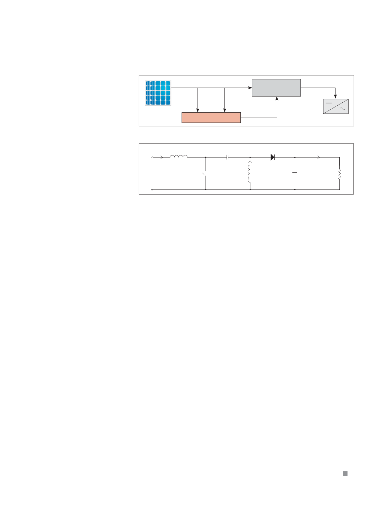
block diagram of an MPPT is shown in
Figure 5.
Essential to the operation of an MPPT is a
buck-boost DC-to-DC converter. This circuit
can increase the panel voltage or decrease it
depending on the switching duty cycle of a
transistor switch.
One form of buck-boost is the single-
ended primary inductor converter (SEPIC).
It is shown diagrammatically in Figure 6
presenting an input resistance that varies
with pulse width modulation of the
transistor switch S.
Maximum power from the solar panel is
transferred when the source resistance of
the panel is equal to the input resistance of
the converter. By adjusting the duty cycle
the input resistance can be made to match
the source resistance of the solar PV panel
or array.
The SEPIC converter can step up and
step down input voltage while maintaining
the same polarities for both with respect to
ground.
When the switch S is closed, the inductor
L
1
builds up a magnetic field, whereas
the second inductor L
2
is ‘charged’ by the
coupling capacitor C. When the switch
S turns off, L1 and L2 feed current to the
RC load circuit.
By modulating a small AC signal on top
of the switching frequency, and comparing
the AC voltage and average panel voltage,
the maximum power point can be located.
INVERTERS AND MORE INVERTERS
The Clean Energy Council (CEC) lists
about 400 approved grid-connected
inverter models, and our listing of a dozen
manufacturers is a drop in the bucket.
However, armed with a bit more
knowledge, you should be in a better
position to ask questions of suppliers.
Features such as communication
are important, although not dealt with
here. Given that the basic technological
requirements are met, other features such
as IP rating, weight, information display, etc,
may rank higher.
What should you look for in addition
to reliability, good documentation and
availability of service?
Electrical Connection
does not
recommend one set of specifications over
another, simply offering some general
observations.
We think the salient points are MPPT
operating voltage range, number of MPPTs
and power factor control.
A larger voltage range allows more
panels to be placed in series (CEC limits the
maximum voltage to 600V DC), this being
preferred to paralleling. Two MPPTs or more
will allow panel arrays to be better distributed
for maximum insolation. Power factor control
is also likely to be increasingly important.
Figure 5.
Figure 6: Circuit diagram of a SEPIC converter.
Solar panel
MPPT controller
Voltage
sensor
Current
sensor
Control
via DAC
Inverter
Power
Power
DC–DC power
converter
+
+
L
2
S
C
-
-
I
o
I
i
+
-
V
C
R V
0
V
i
I
2
-
+ V
D
L
1


