
www. e l e c t r i c a l c o nn e c t i o n . c om . a u
5 3
with
Phil Kreveld
There are three main ways of dealing with
the leakage current:
>
interposing a high-frequency transformer
(basically part of a switched-mode DC to
DC converter);
>
isolating the DC link by transistor switches
in lines supplying the inverter; and
>
providing a neutral voltage point on
the PV supply (eg: through the use of
capacitive dividers).
Some of the schemes are shown in Figure 4.
The HF transformer version (not
illustrated) has very low inter-winding
capacitance, thus isolating the PV panels.
The trick is to achieve low leakage while
holding construction costs down by
reducing the number of components.
In Figure 4a the H5 topology is shown
(note: this is patented technology).
The inverter switching pattern is based on
unipolar modulation whereby T1 is closed
for one half-cycle, and T2 is closed for the
next half-cycle – with T3 and T4 being the
‘within half-cycle’ modulating switches.
The important difference with the H4
circuit is that the PV isolating switch (T5)
operates in unison with T3-T4, thus isolating
the PV panels from freewheeling current.
During the freewheeling phase there are
two paths for this current. During the positive
half-cycle the current flows through the
T3 diode and closed switch T1. During the
negative half-cycle, the freewheel current
flows through T3 and the diode of T1.
In the circuit 4b, sometimes referred to as
‘full H’, T1 and T4 switch at grid frequency
with T5-T6 and T3-T2 being switched at high
frequency. PV isolation is achieved, but the
component count is high.
Figure 4c shows the HERIC (highly
efficient reliable inverter concept) topology.
Note that in this circuit the PV panels are not
isolated. However, the freewheeling path
has been cleverly instituted by T5 and T6
across the output of the inverter.
During the positive half-cycle T6 is closed,
and T5 closes during the negative half-cycle.
T3 and T2 switch on alternately for the
positive and negative cycles respectively.
T1 and T4 switch at high frequency to
provide pulse width modulation.
The T5-T6 and diode combinations confine
the freewheel current to the output circuit.
The last schematic shows the neutral
point clamp (NPC) circuit.
T2 is on during the positive half-cycle
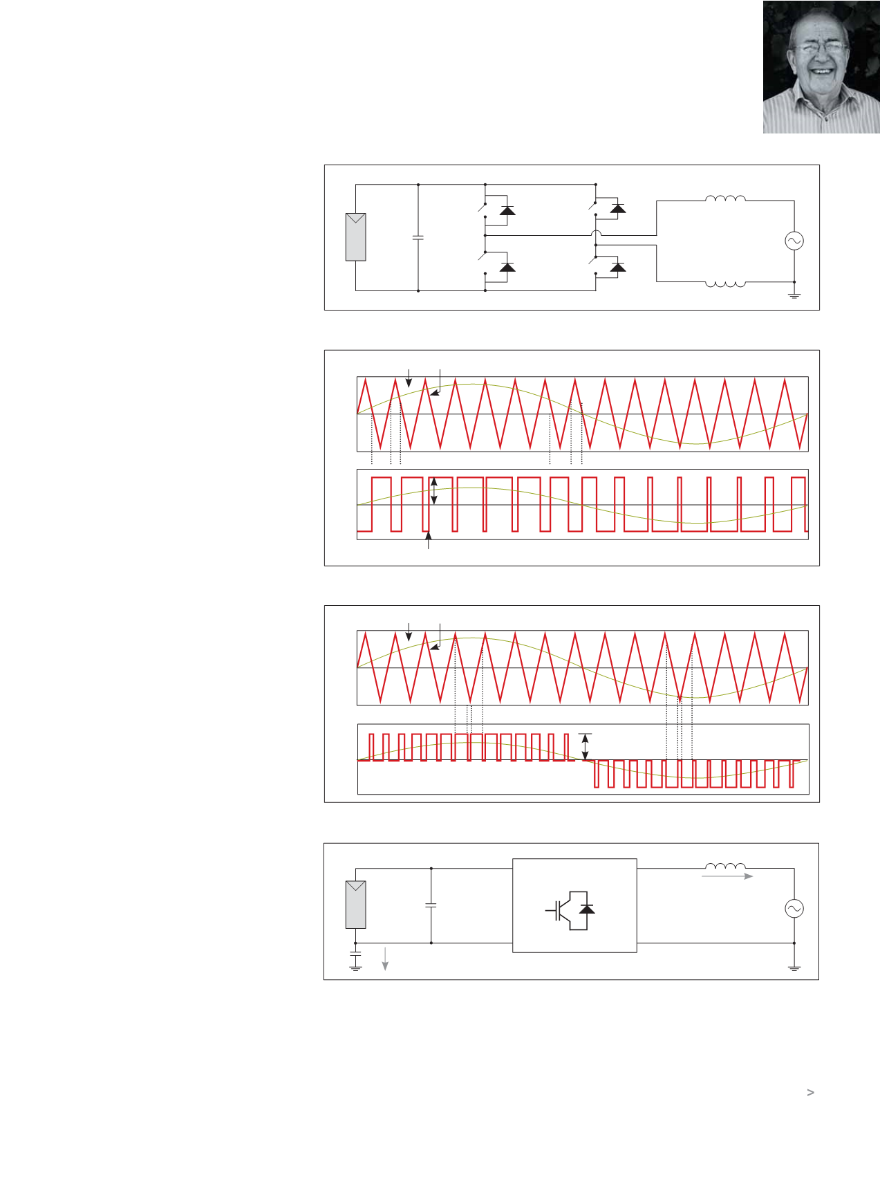
Figure 1.
Figure 2a.
Figure 2b.
Figure 3.
S1
S3
+
-
S2
S4
L1
L2
P
N
V
V
S
A
B
P
+
A
B
-
L1
N
V
dc
i
c-p
C
p
i
S
E
V
S
INVERTER TOPOLOGY
V
m
V
cr
2∏
∏
1.0
0
-1.0
V
AB
0
-V
d
-V
d
V
m
V
cr
2∏
∏
1.0
0
-1.0
V
AB
0
-V
d


