
5 4
E L E CT R I C AL CONNE CT I ON
W I NT E R 2 01 5
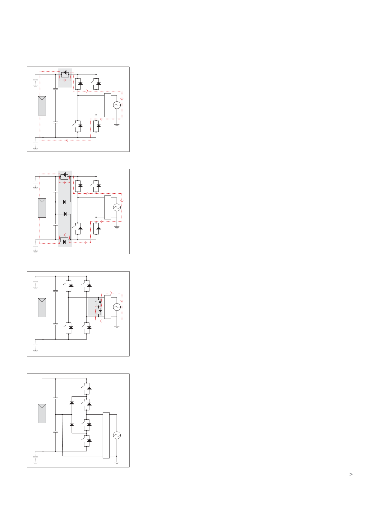
and T3 is on for the negative half-cycle. T1
and T4 switch at high frequency.
The freewheel path during the negative
half-cycle is via T3 and D6, and conversely
through D5 and T2 during positive
half-cycles.
The capacitive divider provides an
almost constant common mode voltage,
thus reducing the possibility of PV leakage
current.
There are many more topologies,
but manufacturers don’t provide much
information on this subject.
EFFICIENCY CONSIDERATIONS
Inverter efficiency is determined by power
loss in the switching transistors and diodes.
The fewer switching components the
better off you are – but, as with all rules, the
proof of the pudding is in the eating.
Thus the full H (4b) inverter has the
highest losses, whereas H5, HERIC and NPC
are substantially lower and close to one
another.
How important is efficiency? Based on
a 20-year life, the opportunity cost of one
percentage point could be in the order of
$16,000. This is in some ways simplistic, the
assumptions being a system with average
power of 2kW over six hours per day and at
18 cents per kW/h.
Inverter efficiency is a matter of weighting
the efficiency levels at various percentage
loadings so as to provide a balanced picture.
There are two accepted ways of specifying
inverter efficiency: the European weighting
and the California Energy Commission (CEC)
weighting. The formulas are shown below.
California Energy Commision (CEC)
weighted efficiency:
ŋ
CEC
= 0.04.ŋ
10%
+ 0.05.ŋ
20%
+ 0.12.ŋ
30%
+ 0.12.ŋ
50%
+ 0.53.ŋ
75%
+ 0.05.ŋ
100%
European weighted efficiency:
ŋ
EU
= 0.03.ŋ
5%
+ 0.06.ŋ
10%
+ 0.13.ŋ
20%
+ 0.10.ŋ
30%
+ 0.48.ŋ
50%
+ 0.20.ŋ
100%
Percentages shown in subscript are of
the inverter’s rated output. In practice,
factors such as dirt and grime build-up,
overshadowing, localised heating of the
panels, etc, are likely to swamp energy
efficiency considerations of only the inverter.
POWER FACTOR (IF NOT UNITY)
Before letting go of freewheel current, we
need to look at power factor.
Although there are exceptions, inverters
usually operate at unity power factor for
the obvious reason that they are controlled
in essence by grid voltage. Thus the
inverter switches current in phase with the
grid voltage.
So what happens to loads requiring reactive
current? Well, that’s supplied by the grid.
Think for a moment about an inverter
as used in a variable-frequency drive
supplying an induction motor. The reactive
current of the motor is fed back to the
DC link via the diodes, but that is for an
‘isolated system’.
Power factor is becoming very important.
As explained above, a grid-connected
inverter is a unity power factor device. From
October 1, 2015, Energex in Queensland will
make it mandatory that every solar power
inverter greater than 3kW in size has reactive
power control set to 0.9 lagging.
This has been introduced to minimise
over-voltages on the electricity network. It
will also reduce nuisance tripping of solar
power inverters and interference to other
customers in the local area.
The Energex requirement will mean
an increase in the rating of inverters (3kW
would become 3.33kVA).
Power factor, like spinning reserve, is
an increasing headache for generation,
transmission and distribution people.
Percentage-wise, they have to supply
more and more reactive load as rooftop
solar pushes more and more kilowatts into
distribution system.
When connected to reactive loads,
isolated inverters ‘automatically’ cope with
them, as does the inverter for a motor drive.
Grid-connected inverters can have less
than unity power factor, and some (see
Figure 4d.
Figure 4a.
Figure 4b.
Figure 4c.
FILTER
B
A
T1
T2
T3
T4
T5
T6
C
G-PV
C
dc
C
dc
PV
T1
T3
T2
T4
V
PE
C
dc
C
dc
PV
D
5
D
6
FILTER
FILTER
B
A
T1
T2
T3
T4
C
G-PV
C
dc
C
dc
T5
T6
D7
D3
PV
FILTER
B
A
T1
T2
T3
T4
C
G-PV
C
dc
C
dc
T5
PV


