


 58 / 116

58 E L EC TR I C AL CONNEC T I ON
AU T UMN 20 1 7
VRLA batteries are prominent, but
so are lithium batteries because of
their high ratios of energy to weight.
More varied than for lead-acid types,
the chemistry for lithium batteries is
outlined below:
The cathode in such batteries is a
lithiated metal oxide, and the anode
is made of graphitic carbon with a
layered structure. The electrolyte is
made up of lithium salts dissolved in
organic carbonates.
When the battery is being charged,
lithium atoms in the cathode become
ions and migrate through the
electrolyte towards the carbon anode
where they combine with external
electrons and are deposited between
carbon layers as lithium atoms. The
process is reversed during discharge.
In outline, efficiency is close to 100%
and life span approaches 3000 cycles
at 80% depth of discharge. Operating
temperature ranges from –30ºC to
60ºC, energy density is 90-190Wh/
kg and self-discharge is about 1% per
month. However, the higher cost is due
to special packaging needs and internal
over-charge protection.
On the basis of amp-hour ratings, the
cost comparison with VRLA batteries is
unfavourable. Yet when depth of discharge
is considered the picture changes.
It is generally accepted that the
most economic and practical DOD for a
VRLA-AGM battery is 50%. For lithium-
iron-phosphate (LiFePO4 or LFP) – the
safest of the mainstream Li-ion battery
types – 80% DOD is used.
CHARGING
The main aim in charging lithium
batteries is temperature control to
minimise the effect of lithium plating of
the anode.
Much depends on the physical
design. A thin, highly porous anode
works best for very fast charging –
rates as high as 1C.
Undercharged lithium batteries
lose capacity permanently, requiring
special precautions on recharge
circuits. Lithium-ion batteries cannot
absorb overcharge. When they are
fully charged, the charge current must
be cut off. A continuous trickle charge
would cause plating of metallic lithium
and would compromise safety.
Over time, the open circuit voltage
will settle to between 3.70V and 3.90V
per cell. A typical charge profile for a
single cell is shown in Figure 7.
For a partly discharged cell, a pre-
charge precedes the transition to
constant current charging. Monitoring
of cell voltage is essential, in order to
switch over at the correct voltage to
constant voltage charging.
When dealing with battery packs,
equalisation of voltage between the
cells is very important.
Unlike lead acid batteries, which can
equalise simply through out-gassing,
there is no natural equalisation
mechanism for lithium batteries.
Their employment in strings and
parallel strings requires that unequal
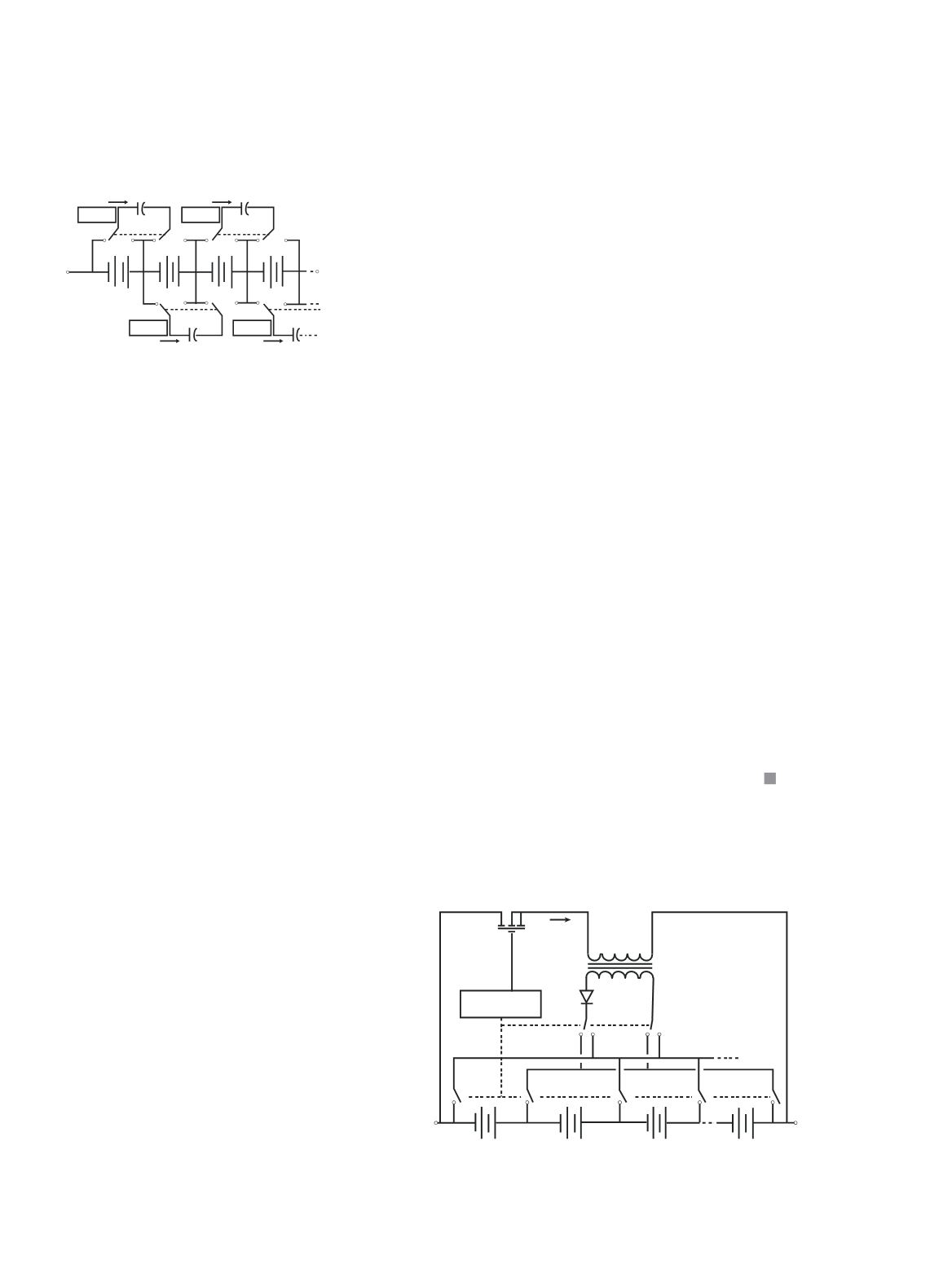
cell voltages be eliminated. Methods for
achieving this include flying capacitor
circuits and many others. The flying
capacitor circuit is illustrated in Figure 8.
Capacitors constantly switch between
cells, thereby swapping charge from
higher-charged cells to lower-charged
cells. Each capacitor requires simple
controls to activate the switches.
There are other methods, such as the
switched transformer method.
Figure 9 shows the stack voltage
being chopped by the transistor-control
circuit, which also monitors individual
cells, and the rectified voltage from
the transformer secondary replenishes
individual cells.
As will be evident, the voltage
equalisation circuitry as described
can form the basis of a battery
monitoring system. This has been
used, possibly experimentally, in some
commercial vehicles.
Control
3 3
I
3
B
3
B
C
4 4
I C
Control
Control
1 1
I
1
B
2
B
C
2 2
I C
Control
Figure 8: Voltage equalisation with flying
capacitor circuit.
n+1
S
4
S
3
S
2
S
1
S
D
T
n:1
I
1
B
2
B
3
B
n
B
Control
Figure 9: Switched transformer voltage equalisation.