


 57 / 116

www. e l e c t r i c a l c o n n e c t i o n . c om . a u
57
powered by potential and current
transformers. However, many are now
electronic, using microprocessors and
requiring a constant DC power supply
– or at least as an alternative if the
normal energising is via a switch mode
power supply.
Although we are focusing on
batteries, charger functions should
also be checked. The challenge in
the above arrangement is to provide
stable voltage under normal operation
and appropriate voltage for the float
charging process.
Furthermore, account must be taken
of operating with parallel battery
strings, and protection – for example,
ensuring that one battery’s shorting
does not affect the others.
A very important parameter in
chargers is ripple. The AC ripple sitting
on top of the DC current component is
deleterious to batteries. It may not be
an intuitive reaction if one looks at a
sine wave about a DC level. There are
as many peaks going higher than the DC
value as there are troughs below.
That might lead you to conclude that
the net result is simply the effect of the
DC component only. However this is not
the case. The actual rms (heating value)
is given by the formula:
In the formula, I
eff
is the effective
charging current, I
DC
is the DC
component, and I
AC
, the AC component.
In substation maintenance,
testing ripple is crucial. If the voltage
ripple is sufficiently large during
negative excursions to be under the
open circuit cell voltage, discharges
will take place.
The current ripple component
provides additional heating. For
minimal heating influence on the
battery banks, ripple voltage should be
well under 2% peak to peak, and under
4% peak to peak if discharge effects are
to be avoided.
Although DC circuits in substations
vary widely, there are several aspects
that must be taken account of. The first
one being protection against battery
cell shorts.
The principle of the circuit is shown
in Figure 5, in which two parallel
strings are shown by way of example.
The circuit would also apply to a large
number of parallel strings.
The underlying assumption is that,
apart from forward voltage drops in
the steering diodes, the load and the
batteries can use the same voltage. Yet
that is often not the case.
If a battery cell or cells shorts in the
second string then diode D3 will be
reverse biased. Charging of the string
can still take place via D4, but
no current can be drawn from the
first string.
In many applications, a float charge
service is required whilst supplying
the critical load during normal
operation. In this instance charging
current must be limited. The circuit
shown in Figure 6 fulfils this function
by means of a current-limiting resistor.
The battery string discharges via the
diode when main power fails.
Substation power supplies
incorporating charging functions can
be provided with a number of
important features, including high and
low voltage alarms, AC and DC output
status, ripple alarm and battery ground
detection for floating DC supplies.
A battery ground-detection system
uses a resistive voltage divider so that
positive and negative terminals of the
battery bank maintain equal magnitude
voltage values with respect to ground.
The resistive divider has an added
benefit, namely to function as a
bleed-off for any capacitively coupled
voltages that might interfere with the
operation of protective relays.
As a further improvement, battery
monitoring can be installed. This is
generally based on measuring two
important parameters: cell voltage
and impedance.
One method involves the injection
of a very small high-frequency current
and measurement of the voltage drop
across the cell. Battery impedance
coupled with open circuit cell voltage
provides a very good ‘state of health’
for batteries.
TRACTION
Smaller vehicles are the focus here,
including forklifts, ground equipment
for airports, and short-range transport.
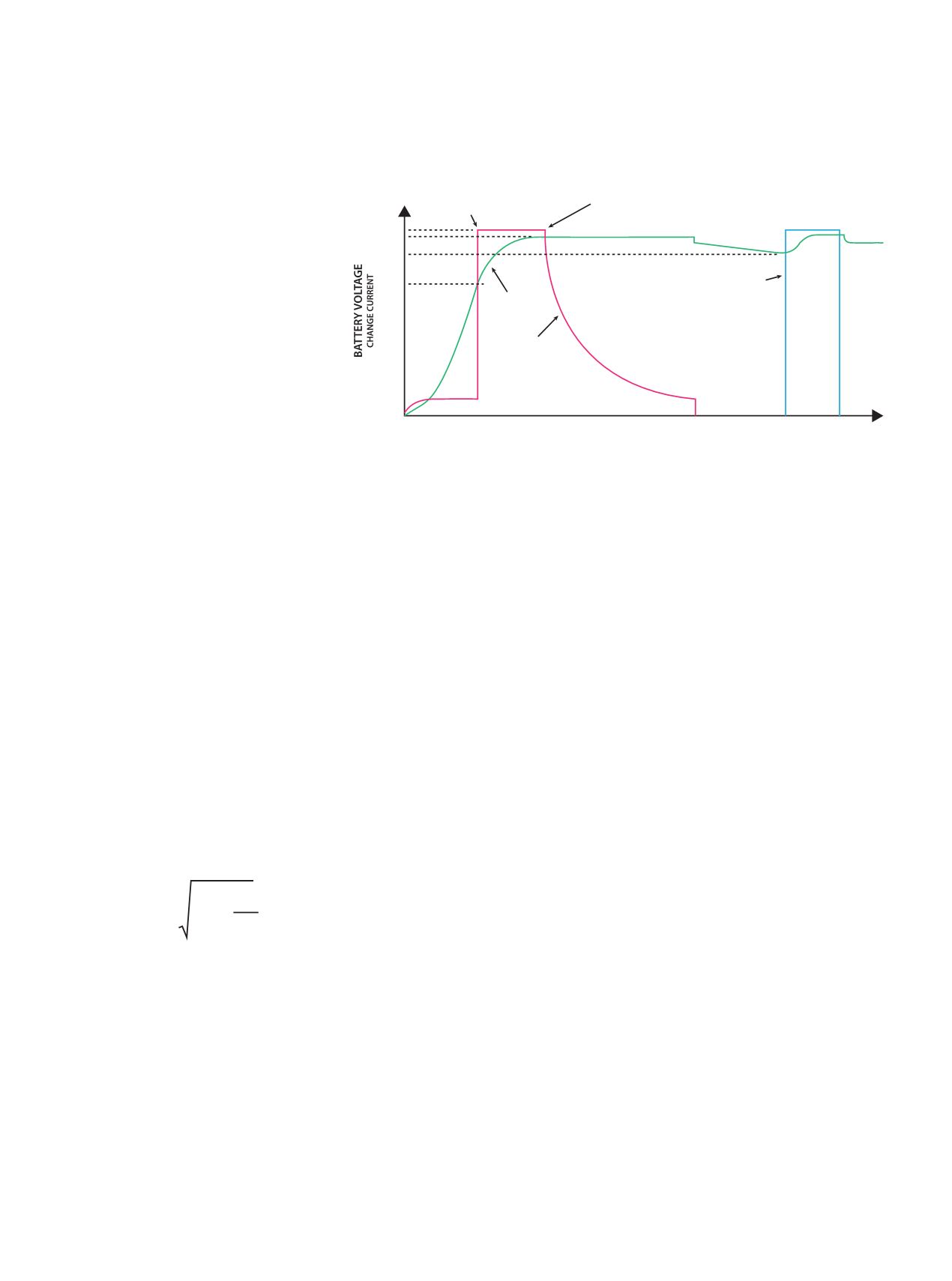
CC to CV transition
4.1 (Default)
Proqualification to Fast
ChargeTransition
1C
3V
4.1V
3.9V
0.1C
Battery
Voltage
Battery
Current
End of Charge
Current
0.1C (Default)
Charge
maintenance
pulse
TIME
I
I
2
= +
eff
2
DC
I
2
AC
Figure 7: Charging profile for a Li-ion cell.