


 55 / 116

www. e l e c t r i c a l c o n n e c t i o n . c om . a u
55
lead-acid (VRLA), vented nickel
cadmium (Ni-Cd), and recombinant
nickel cadmium (RNi-Cd). The testing
regimes have to be appropriate to
battery capacity characteristics.
The lead-acid VLA and VRLA require
frequent testing by the time 80% of
capacity is reached. Thereafter the
testing frequency should be increased
to yearly intervals.
With the Ni-Cd batteries, the test
frequency should be at five-year
intervals – and when at 90% of rated
capacity it should be annual. The thing
to realise is that rated life is a bit like
how long a piece of string is. Figure 2
makes that plain
Regardless of the amp-hour capacity
of a particular battery, the more
discharge cycles it is subject to the
shorter its lifespan will be. Battery
tests, if they include a 100% depth
of discharge (DOD) will, as the graph
illustrates, shorten life the most.
Battery maintenance practice should
include amp-hour data collection.
(This is not a DOD statistic, since float
charging takes place – or usually can be
expected between discharge events.)
The VRLA battery is the most
popular type in substations. Its
one-way valve can, in cases of over-
charging, vent gases (hydrogen and
oxygen) but that’s not what should
usually take place.
In VLA (flooded cell) batteries the
creation of hydrogen gas, H2 and oxygen
radicals (1/2-O2) causes water loss in
the electrolyte, and a reduction in the
electrolyte specific gravity resulting a
decrease in cell open-circuit voltage.
In VRLA batteries the electrolyte
is immobilised by means of a porous
separator between the positive plate
(lead oxide) and the negative plate
(lead, in sponge form). The separator is
an absorbent glass mat (AGM) trapping
the oxygen – or, better put, making the
gas diffuse slowly to the negative plate
where lead oxide is slowly formed
during the battery discharge.
Despite the inherent ruggedness
of VRLA batteries, over-charging will
lead to oxygen generation in excess of
the AGM’s ability to trap the gas, and
out-gassing will occur via the one-way
valve. If the over-charging continues,
a premature drying out will occur
with a permanent loss in capacity.
The recharging process is therefore
very important.
Given a battery’s capacity, C, in amp-
hours, the total charge that needs to
be replenished in order to restore its
capacity is of the order of 1.10C. There’s
no such thing as a free lunch, and more
energy needs to be put in than will be
extracted during the discharge.
The energy loss in a battery during
charging is I
2
r
b
where I is charging
current and r
b
, the internal resistance.
The specifics of battery charger
operation are crucial for substations.
They form part of the general DC
power requirements during normal
operation, thus requiring some special
circuit considerations.
Under normal operation only the
charge loss due to internal charge
leakage needs to be made up. The
process is variously referred to as
trickle charging or float charging.
Irrespective of the semantics, making
up for more than the charge lost will
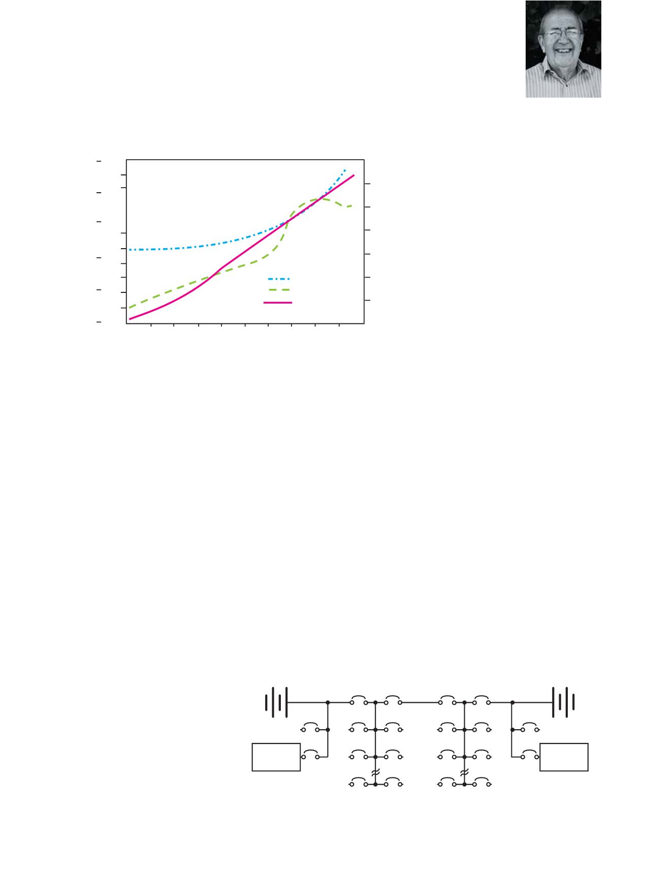
Charging
Voltage Degrees C
Time in Hours
AH% Restored
Temperature
Voltage
AH%
20
55
50
45
40
35
30
25
20
15
10
20
20
20
20
100
120
140
5
0
0 1 2 3 4 5 6 7 8 9 10
0
18
16
14
12
10
Battery
Bank A
Auxiliary DC
Supply Panel A
Main
Tie
A1
A2
A3
A4
An
An
N.O.
Tie
Main
B1
B2
B3
B4
Bn
Bn
N.O.
Auxiliary DC
Supply Panel B
Load Bank
Connection
Battery
Bank B
Load Bank
Connection
Battery
Charger A
Battery
Charger B
Figure 3: Constant current charging of a VRLA battery.
Figure 4: Typical redundant layout for a substation.
BY
PHIL
KREVELD