


 56 / 116

56 E L EC TR I C AL CONNEC T I ON
AU T UMN 20 1 7
shorten battery life in the long term.
Charging current Ic is equal to the
difference in charger voltage and cell
voltage divided by the total resistance,
which takes into account any current-
regulating resistance, circuit resistance
and cell internal resistance.
The higher the charging rate, the more
quickly cell voltage rises, necessitating a
further increase in charging current and
a rise in cell temperature.
Figure 3 shows the process for a 5C
charging rate, that is, a 200A-h battery
would be bulk charged initially at 40A.
As the graphs show, temperature rises
slowly initially but then takes on an
exponential slope. It is clear that to
prevent excessive temperature the
rate of charge should be decreased as
the battery approaches 80% charge.
BATTERY CHARGERS
Before looking at substation DC
power reticulation, charging circuits
should be examined.
A constant voltage charger should
in the first place have an output
above the highest open circuit cell
voltage. It has the advantage that
current decreases as the battery
gains charge, but its charging rate will
be considerably slower than with a
constant current source.
However, such a charger should have
a way of stepping the charger current
down as the battery gains charge.
For substation duty some form of
charger temperature compensation
is important. This also applies to the
battery bank room, which ideally should
be held within a tight band of 15-25°C.
Temperature has a substantial
effect on float current provided by
a constant voltage source. The float
current must roughly double for each
10°C rise in cell temperature.
Increased heating of cells and
reduced heat flow from batteries
increases the risk of thermal runaway.
Higher ambient temperatures are
obviously implicated here.
This effect is particularly observed
in VRLA batteries rather than in
vented (flooded) cells, because the
formation of oxygen is an exothermic
reaction. In the case of sealed VRLA
batteries, the heating effect and joule
losses can add up very quickly to
higher temperatures.
The ability to de-sulphate the
negative plate, which gains a layer
of lead sulphate as the battery
discharges, is an advantage. Some
chargers incorporate a de-sulphating
pulse, although its mechanism is not
well understood, and some chargers
use a form of pulse width modulation
to control the charging process.
This latter method combines the
advantage of constant current
charging with the inbuilt feature
of tapering current of constant
voltage chargers. Using pulse width
modulation, the current pulse width
is reduced by means of an algorithm
and/or a suitable feedback mechanism
based on cell voltage.
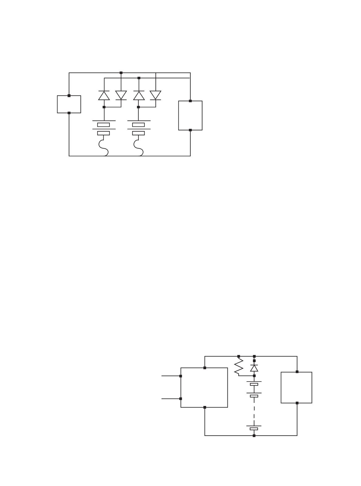
DC CIRCUITS
Substation DC circuits vary, but
there are some generalities as shown
in Figure 4.
In the dual-battery system as shown,
the chargers A and B function not only
to trickle charge the two banks but
also to supply the various DC circuits:
that is, DC coils for circuit breakers, DC
motors for energising trip springs, and
protection relays.
Electro-mechanical versions are
D1
+
+
+
+
-
-
D2
Ba
Fa
Fb
Bb
D3
D4
Load
Charger or
Rectifier
54 DC
Power Supply
and Battery
Charger
C1
C2
C24
Rc
D
+
+
+
24 Cell
48 VDC
Battery
Commercial
AC Power
Input
Critical
Load
Figure 5: Protection of parallel strings.
Figure 6: Parallel supply of load and float charge.