
40 E L EC TR I C AL CONNEC T I ON
S PR I NG 20 1 6
basically to provide a wider selection
of rated current with a large degree
of overlapping.
At the contactor level more attention
is claimed to have been focused on
contact design and
physical layout.
The latter is important, as high
currents can cause repulsion forces and
chattering, with deleterious effects.
According to some manufacturers
the thermal protection area (not
usually considered a challenging area)
is best served by electronic rather
that the usual bi-metallic relays. It is
hard to argue with this concept, as
the use of I
2
–time algorithms is hard
to beat in terms of repeatability and
lack of memory effect.
The use of overlapping current
ranges allows a designer to pick a
range in which the rated current of
the motor is in the lower quartile of the
rated current range of the protection
device – it being assumed that the
‘instantaneous’ trip is an integral part
of the protection circuit.
It can also be provided by a moulded-
case breaker. By picking the low end
of the protection range, the maximum
multiplier available is likely to cover the
inrush current.
To further explore this, consider the
situation in which the upper quartile of
the protection range has been selected.
The inrush current is now likely to
cause a false trip.
Take this example of two motor
starter protectors for a 15A rated
motor:
>
A – setting scale 10; 16A, multiplier
of 13.
>
B – setting scale 14; 20A, multiplier
of 13.
Motor starter protector B is
recommended, as its power loss is
lower and it has a 5A clearance to the
top protection setting. Protector A has
a 1A clearance.
The power loss of B is about 35%
lower than that of A. This is because
the latching current of the starter coil
is proportionally smaller.
>
For A the response value of the short-
circuit release is 208A (13A x 16A).
With a rated motor current of 15A, the
short-circuit release is 13.86 times the
setting current (208A/15A = 13.86).
>
For B, the response value of the short-
circuit release is 260A (13A x 20A).
With a rated motor current of 15A, the
short-circuit release is 17.33 times the
setting current (260A/15A = 17.33).
Because the ratio of inrush current
to rated current is substantially
increased for B, it is the better choice
for an ie3 motor.
As a final word, measurement of the
inrush current is highly recommended
when critical applications are involved.
It removes to a large extent a
‘guesstimation’ element.
The instrumentation involved need
not be highly complicated. Clamp-on
testers are available that can record
the inrush peak.
As ratings increase, some form of
soft starting is likely to be used.
On the other hand, when full
power has to be close to
instantaneously available, and in
particular if high inertia loads are
involved, a waveform recorder is
the best analytical device to
determine the motor starter and
protection requirements.
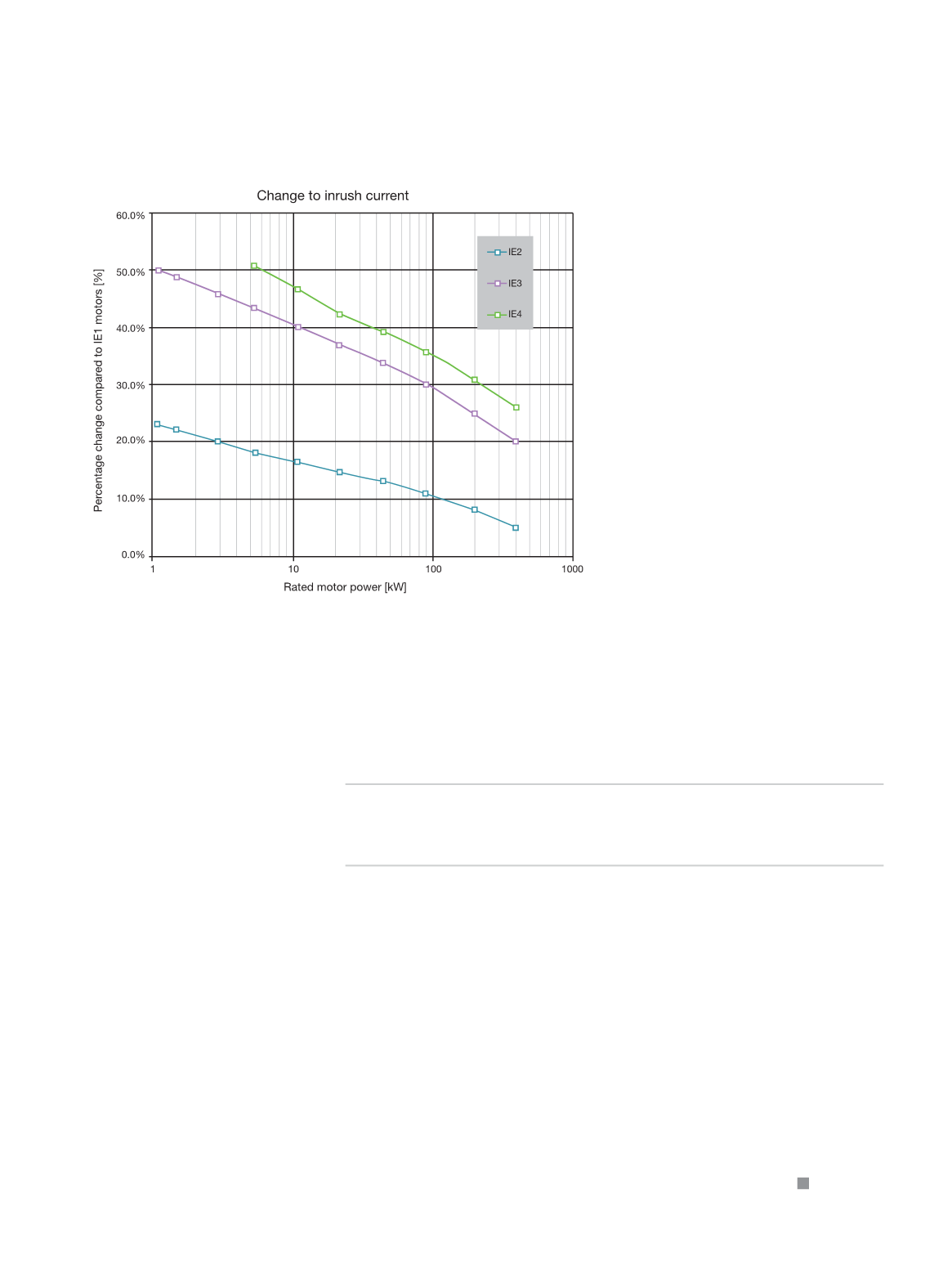
Figure 3: Inrush current as a percentage of in-rush current in ie1 motors.
Inrush current for high rating DOL starts is best
measured before selecting motor protection.


