
www. e l e c t r i c a l c o n n e c t i o n . c om . a u
39
of the motor falls somewhere within
the protection range of the overload
device.)
Suppliers of motor starter and
protection control gear claim that,
because of such tripping, higher-
rating protective devices are chosen
rather than devices based on the
specifications.
This is not a smart way to deal with
false tripping, because the higher-
rating protective device will probably
affect the tripping characteristics of
the thermal overload. It is difficult to
gauge how often this scenario plays
out, but the engineering literature
yields enough examples of starting
problems to merit alerting our readers.
Figure 1 shows the familiar torque
versus speed characteristic of a typical
induction motor. The current graph is
superimposed.
The zero speed torque or locked
rotor torque and current are high, in
particular the current, which will be
six or eight times the rated current
flowing at rated speed.
It is often thought that the locked
rotor current is in fact the inrush
current, but that is not the case. When
a motor is connected to supply, the
first aspect is that the stator magnetic
field has to be established.
The stator winding does not yet
represent a sort of transformer with
fairly substantial leakage inductance
– everything is in ‘flux’ – until the
magnetic flux is present in the air gap
between stator and rotor.
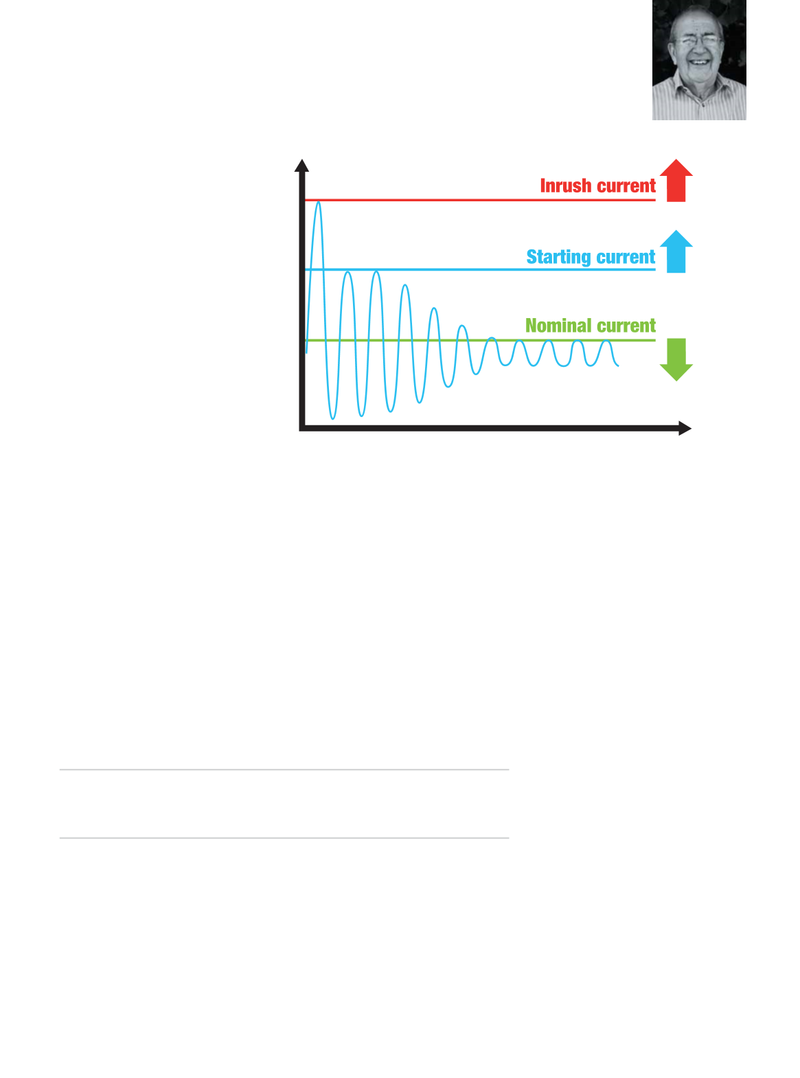
During this time, which lasts less
than one cycle but could stretch to
several cycles, the current looks
like a sine wave stuck on top of an
exponentially decaying DC component
(see Figure 2).
For your ‘common or garden’
induction motor of yesteryear, the
inrush current (the current flowing
before the locked rotor current level is
reached) might typically be eight to 12
times rated current.
The ie3 motors have much higher
inrush currents, lower locked rotor
torque and, for the same kilowatt
rating, a lower rated current.
This latter feature stands to
reason, because kilowatts are equal to
power factor multiplied by voltage and
line current.
It is fair to assume that power factor
is more or less the same for motors of
low and high efficiency at rated speed
and load, so line current must be lower.
Building high-efficiency motors
in the first place involves reducing
rotor resistance to reduce I
2
R losses.
The magnetic design also has to be
somewhat different, resulting in a
different input resistance to reactance
ratio at the stator terminals.
This all sounds scientific, but we
can leave that – save to note that
the higher resistance is relative
to reactance the sooner the DC
component decays.
However, for high-efficiency motors,
resistance is lower and therefore the
peak value of current and the decay
time are higher.
As can be seen in Figure 3, the ratios
of inrush current to rated current go
up as we climb the efficiency scale. In
fact, a level as high as 20 times rated
current is not uncommon.
As stated, rated current is lower for
high-efficiency motors. As you would
expect, this accentuates the ratio of
inrush to rated current.
So what are the implications for
motor starter and protection gear?
Manufacturers with a European
bent, so to speak, claim to have made
accommodations in their designs.
At the protection level this is
Figure 2: The difference between inrush current and starting (locked rotor) current. The
current looks like a sine wave stuck on top of an exponentially decaying DC component.
Unless the protection level is chosen wisely there
is a chance of tripping on starting the motor.
BY
PHIL
KREVELD


