


 46 / 116

4 6
E L E CT R I C AL CONNE CT I ON
AUTUMN 2 01 5
A 3% voltage drop = 0.03 x 230 = 6.9V
(this value must not be exceeded).
The current for the calculations will be
8A, as the socket outlets will be distributed
along the circuit (refer Clause 3.6.2
exception 1 of the Wiring Rules).
The impedance method:
The resistance of the cable is found by
using Table 35 of AS/NZS3008.1.1 and the
75°C value, i.e.: 9.01Ω/km.
Vd = I Zc
= 8 x 9.01/1000 x 40 x 2 (don’t forget
there are two conductors, the active and
the neutral return).
= 5.8V. This value passes the 3%/6.9V
voltage drop requirement set by the
installation requirements.
The mV/Ammethod
The Vc value is found for the 2.5mm²
cable using Table 42 of AS/NZS3008.1.1 and
the 75°C value, i.e.: 15.6mV/Am
Vd = (L x I x Vc)/1000
= (40 x 8 x 15.6 x 1.155)/1000 (don’t
forget the 1.155, as the mV/Am value in the
table is for a three-phase circuit)
= 5.8V
Both methods align – we must know
what we are doing! Again this passes the
3% requirement.
The simplified mV/Ammethod
Am/%V = (L x I)/%Vd
= (40 x 8)/3
= 106.7 Am/%V
Looking up Table C7 and selecting
the cable with a value not less than
106.7 Am/%V, we find that 2.5mm² is the
minimum size standard cable we can use
for this project. So, we come up with the
same result – it’s 2.5mm² cable.
OTHER CONSIDERATIONS
The Wiring Rules provides Table B1
for maximum route lengths for circuits
based on loop impedance.
This does not consider voltage drop,
so I have created Table 1 to compare
maximum route lengths for loop
impedance with voltage drop in the
same circuits.
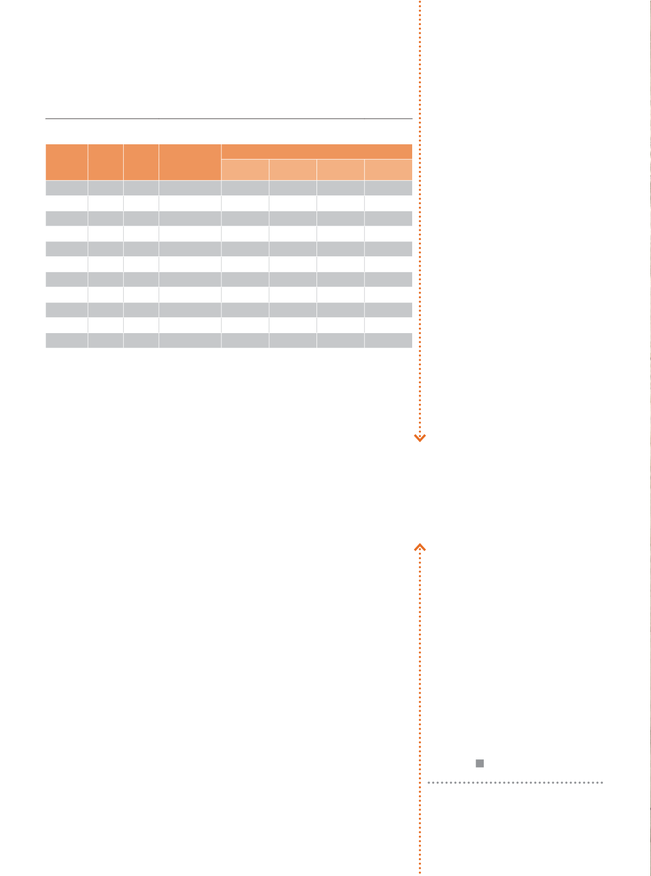
I have also created Table 2, which
converts the values of loop impedance to
voltage drop.
A comparison of both tables shows that,
in most cases, voltage drop requirements
are often more stringent than loop
impedance requirements. Using loop
impedance route lengths or impedance
values in isolation is likely to result in
non-compliance with the Wiring Rules for
voltage drop.
CONCLUSION
Voltage drop must be considered when
designing and installing electrical wiring.
Compliance with voltage drop
requirements will be achieved mainly by
installing a large enough cable.
Total voltage drop in a low-voltage
installation is usually 5%. However, this
can be 7% if the supply comes from
the low-voltage terminals of a substation
on the premises and is dedicated to
the installation.
The allowable voltage drop must be split
between the consumer mains, sub-mains
and final sub-circuits to achieve an overall
compliant outcome.
Maximum route lengths and fault
loop impedance requirements do not
generally ensure compliance with voltage
drop rules.
> PowerLogic
www.powerlogic.com.auTable 2 - Maximum Values of Circuit Resistance from Table 8.2 of the Wiring Rules
Converted to Voltage Drop
Active &
Neutral
(mm²)
Earth
(mm²)
No of
Phases
Protective
device rating
(A)
VOLTAGE DROP
Type B Type C Type D Fuses
1
1
1
6
16.0% 8.6% 5.1% 19.2%
1
1
1
10
16.0% 8.5% 5.1% 17.8%
1.5
1.5
1
10
16.0% 8.5% 5.1% 17.8%
1.5
1.5
1
16
16.0% 8.5% 5.1% 13.6%
2.5
2.5
1
16
16.0% 8.5% 5.1% 13.6%
2.5
2.5
1
20
16.0% 8.5% 5.0% 11.7%
4
2.5
1
25
12.4% 6.5% 3.9% 8.7%
4
2.5
1
32
12.2% 6.7% 3.9% 8.9%
6
2.5
1
40
9.4% 4.9% 3.1% 6.3%
10
4
1
50
9.1% 4.8% 3.0% 5.7%
16
6
1
63
8.8% 4.9% 2.7% 5.5%
Notes: 1. Halve the percentage voltage drop where the load is distributed over whole length of the circuit such as a
lighting or socket outlet circuit.
2. For three phase circuits multiply the percentage voltage drop values above by 0.866."
Designers and installers must
consider voltage drop to ensure
safety and proper operation
of the equipment.