
4 2
E L E CT R I C AL CONNE CT I ON
S P R I NG 2 01 5
SOLAR SWITCHGEAR
No shortcuts for solar
U
sing the right installation
equipment for a photovoltaic
rooftop system ensures maximum
operating life – and customer satisfaction.
When the solar installation industry was
in its infancy there was some excuse, or
at least an understanding, for very poor
choices of cabling, switchgear, junction
boxes and conduit.
There were even instances of AC-designed
switchgear being used for DC carrying
circuits. We hope that doesn’t happen
these days, but there is still much room for
improvement in durability and safety.
If there’s any unfamiliarity on the part of
the installer it is likely to be on the DC circuit
side. The difference is not so much in current
ratings for cables (we are always dealing with
rms AC current as equivalent to the same
value DC current) but in the switchgear.
DC current is difficult to interrupt. There
are no ‘swing through zero points’ for the
arc, which can be drawn on opening a
switch, to be extinguished.
For AC, load-make and load-break are
about the same challenge, whereas for DC
load-make is not a problem but load-break
is. In practice the DC interrupters (load-
break, since there is no way we can stop
the sun from shining on the PV panels)
are bulky compared with their AC current
rating equivalents.
In AC switching, the interruption can
occur anywhere in a 10 millisecond period.
Even the possibility of drawing an arc on
opening the circuit is minimised if that
happens to be near a crossover point. The
speed of opening contacts is therefore less
critical in AC than in DC circuits.
In DC switching, the idea is to build
up voltage across the switch rapidly. If
this doesn’t happen an arc will strike and,
because of its low impedance, current will
continue to flow.
A well-established technique of dealing
with the interruption problem is to use an
arc-extinguishing method. To handle this in
a compact device, rather than an air blast
to lengthen the arc, a permanent magnet
is used.
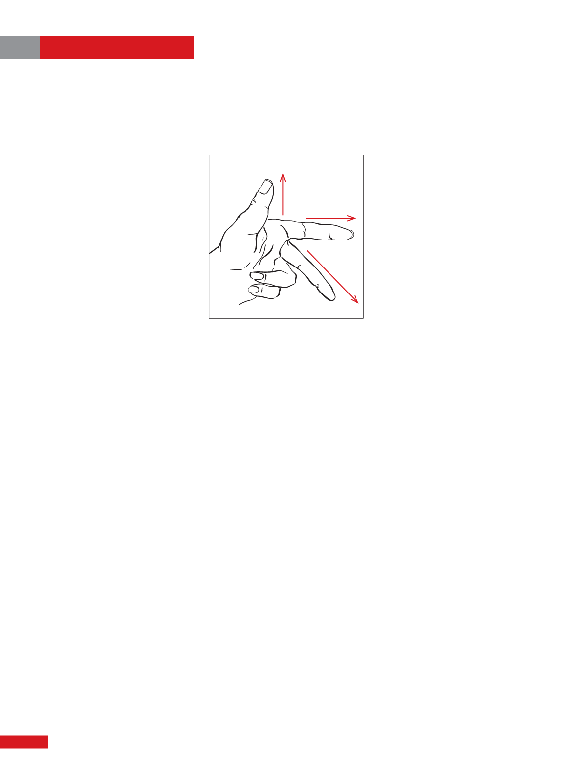
The left-hand rule (Figure 1) shows how it
works. We are relying on the force F to blow
the arc (current-carrying conductor) away
from the contact points.
It’s a neat way of solving a problem, but
the use of such ‘polarised’ devices can be
problematic. If not connected properly (ie:
current polarities not observed), or if current
direction can reverse, the arc will be sucked
in instead of being blown out.
In the case of compact switches, the heat
generated as a result can provide all the
conditions for a fire to start. For this reason,
Australian Standards stipulate that polarised
devices can no longer be used.
The multiple-contact ganged switch,
although bulkier by virtue of three or four
contact sets, is superior. Furthermore, both
conductors in a DC circuit can be interrupted
(this cannot be done conveniently in the
permanent magnet device).
In most installations two isolators are
required: on the roof and at the input to the
inverter. For transformer isolating inverters
you will need a DC breaker or isolator that is
double pole (breaks negative and positive
simultaneously).
Switches should be rated to break 1.25
times the short circuit current (Isc) rating of
the solar PV array and 1.2 times the open
circuit voltage (Voc) of the array. Look
carefully at suppliers and the specs because
this is a critical area of an installation.
If you are aware of polarised switches or
breakers in existing installations, you must
replace them. They are not allowed under
AS/NZ 5033. Ganged switches suitable for
solar installations come in current ratings of
8, 10, 16, 20, 25, and 32 amps, and voltages of
250, 440, 500, 800 and 1,000V.
The rooftop installation is an example of
unprotected consumer mains, though DC
rather than AC. The regulations require DC
conductors, where otherwise exposed, to
be housed in heavy-duty conduit, obviously
resistant to UV degradation and vermin.
Note that in some panel mounting
rails, provision is made for routing cables.
However, the installer needs to ensure that
entry slits are too small for any creatures to
enter. In general, it is better to err on the
side of safety and enclose all conductors in
conduit without over bunching, as this will
lead to heat problems.
In terms of total system cost, DC
conductors account for a small proportion
(2-5%), but bad cabling is responsible for
7-10% of installation problems. In many
instance this has caused a fire.
Electricity from the sun is
cheap, but don’t think that way
about PV installation gear.
Phil
Kreveld
tells how to get the
best out of those essential bits
and pieces.
The left hand rule.
Force
Field
Current


