
52 E L EC TR I C AL CONNEC T I ON
W I N T E R 20 1 6
calculations and material costings.
A detailed design provides the
installation ‘road map’ – site layout
plan drawings, string layout drawings,
elevations, inverter station drawings,
electrical drawings, protection and
zero export schematics, and a bill
of materials.
In addition, a detailed report
explains the design choices and
installation methodology.
An installer can safely follow these
drawings knowing the system will meet
the CEC, Australian Standards and best
practice guidelines.
The GSES design report also complies
with the DNSP document requirements
and can be submitted alongside an
application to connect.
High-quality system designs should
contain the elements set out below.
Site assessment
–
Roof structure,
roof obstacles, building height, shading,
roof type, access and existing electrics.
An assessment can be conducted by
the engineering consultant or by the
installer. When the latter is used, the
consultant provides questionnaires
and forms to the installer to ensure
adequate information transfer.
A site assessment is essential for
completion of the system design.
Plan view diagrams –
Module layout,
module spacing on roof, row spacing,
shading, purlin spacing, and feet and
rail spacing.
System design calculations –
Number
of modules in series and parallel; cable,
isolator and circuit breaker sizes;
maximum power point (MPPT) tracking
configurations; inverter inputs; and
system protection requirements.
Bill of materials –
This is based on
the design drawings and schematics,
allowing the quantities of all major and
minor components to be defined.
String layout and electrical wiring
drawing –
Highlights the module
strings, method of connection and
cable run locations in roof space,
conduit and cable tray.
Financial analyses –
Consumption
data and predicted system yield
information will allow for accurate
calculation of system return
and savings.
CONCLUSION
The system design process and
documentation allows installers to
visualise the installation.
They can then anticipate and
mitigate any issues and provide
accurate data on performance and
financial return to the customer.
The information offers potential for
installation cost savings by reducing
materials requirements and time to
completion, thereby improving margins
for installers.
GSES offers engineering consulting
services, including feasibility studies,
system design, tender preparation and
evaluation, commissioning, inspection
and performance review services.
> GSES
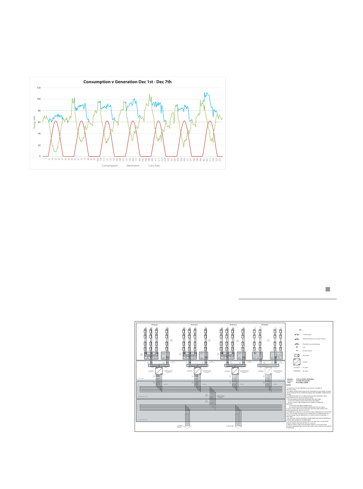
www.gses.com.auData from an interval analysis of the comparison of consumption and generation data
collected using a power analyser or interval meter.
Single Line Diagram (SLD) depicts the electrical connections between the PV array,
inverter, electrical protection equipment and MPPTs.


