
4 4
E L E CT R I C AL CONNE CT I ON
W I NT E R 2 01 5
The MPPT feature of inverters is
important. The role of the MPPT is to adjust
the PV array voltage for maximum power
and to provide a sufficiently high voltage
to the DC link feeding the inverter. (As
mentioned, a single-phase system needs a
DC link voltage exceeding 340V.)
For a PV array on one side of the roof
only, the panels are wired in series and
have to deliver sufficient voltage to the
inverter’s DC link.
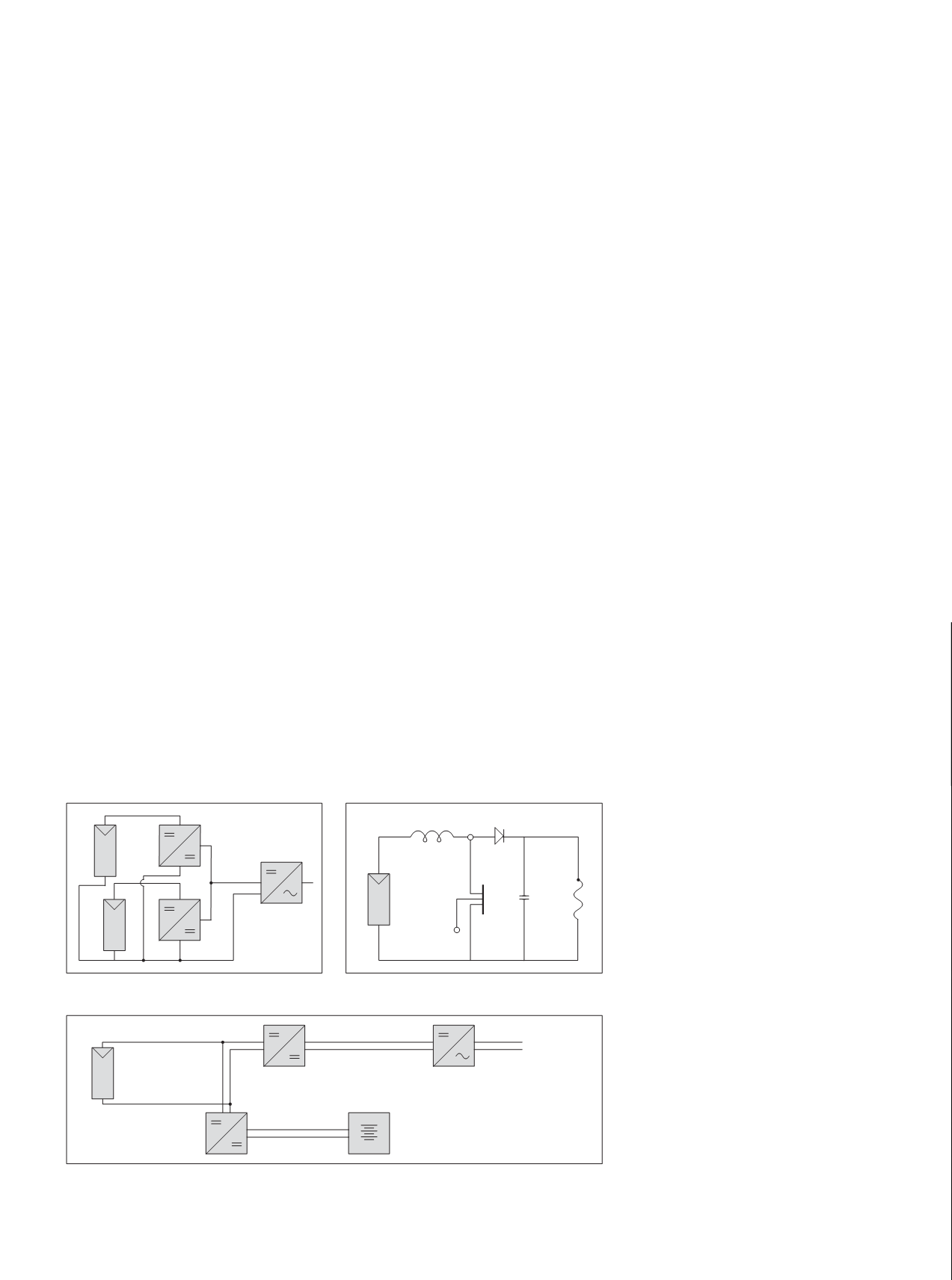
For PV arrays on two sides of a roof, each
has its own MPPT, which has its output in
parallel with the other MPPT to supply the
inverter DC link (Figure 4).
Other than the simple means of MPPT
control by reference to open circuit panel
voltage, all other methods use intricate
software, and technical details are not
supplied as a rule.
MPPT circuits can be visualised as
in Figure 5, which illustrates a typical
boost circuit. The switch (S) is a transistor,
turned on and off at a varying duty cycle
determined by software. That duty cycle is
the ‘guts’ of the power tracking (note that
bucking is also required at times, see article
on page 52).
With the switch closed, current builds up
through the inductor (L). When it opens,
the inductor current flows through diode
(D) to add charge to capacitor (C). The
DC link draws current from the capacitor,
reducing the voltage across it.
Most grid inverters deliver unity power
factor output. The house load may well
have some motors requiring lagging power
factor. Irrespective of feed-in, the grid has
to supply the lagging reactive current to
these loads.
The reason for unity power factor is that
the grid synchronises the inverter, allowing
current from the inverter to flow between
voltage cross over points only. For an off-
grid inverter (basically the same in circuit
design) something different happens.
All inverters have freewheel diodes
connected across the transistors making up
the inverter bridge and these can conduct
current back into the DC link – reactive
current, exactly the same as happens in a
variable frequency drive inverter powering
an induction motor.
A vexing aspect of grid-connected
inverters is ‘over production’ of electric
power. The more the sun shines the more
energy is put into the DC link via the MPPT
and the inverter can deliver more current
to the grid.
Depending on the impedance of the
supply line, the voltage can rise and, because
inverters have top as well as bottom voltage
limits, the inverter will disconnect from the
grid when these limits are exceeded.
This is a real problem where the inverter
is part of a street scene in which every
house has a solar PV system. The under-
voltage limit is a safety measure (anti-
islanding) to allow disconnection should
a power failure or brownout occur. In that
case linesmen don’t want to encounter
voltage unexpectedly.
Although still not commonly available,
grid-connected systems with battery
storage in years to come will be able to
store excess production and use it at night.
Control software, sometimes called ‘peak
shaving’, already exists for commercial
three-phase PV systems.
Grid-connected household systems are
also being installed, although due to price
there are few installations, and more space is
required (one car space less in the garage).
Figure 6 shows a block diagram. In this
system the PV panels charge the battery
bank and supply the DC link of the inverter.
Excess energy is fed to the grid, but at night
the battery bank supplies household needs.
The time may come when households
will be connected by a 10A rather than a
60A service line, because battery storage
will make consumers far less reliant on the
supply grid.
SWITCHGEAR AND SAFETY
A solar PV system must have DC isolation
switches as well as AC switchgear.
DC is much more difficult to interrupt
than AC, which has zero crossover points
every 10 milliseconds. The moment a
DC circuit is interrupted, i.e. the PV array,
its self-inductance will want to keep the
current flowing, because energy is stored in
its surrounding magnetic field.
Figure 6.
Figure 4.
Figure 5.
Solar
PV
DC / DC Converter
Battery
Bank
Inverter
Grid
L
D
S
C


