
www. e l e c t r i c a l c o nn e c t i o n . c om . a u
4 3
with
Phil Kreveld
simpler version is based on a proportion of
the open circuit voltage. In a later article on
inverters there will be more on MPPT. For
the moment it suffices to know that MPPT
is a really crucial part of a solar inverter.
A gable roof (say, with a north-south
roof ridge), can have panels on both sides
to make use of morning and afternoon
sun. The inverter can have two MPPTs
to maximise the individual array power
outputs. For maximum power the panels
should have identical characteristics.
SHADING AND ORIENTATION
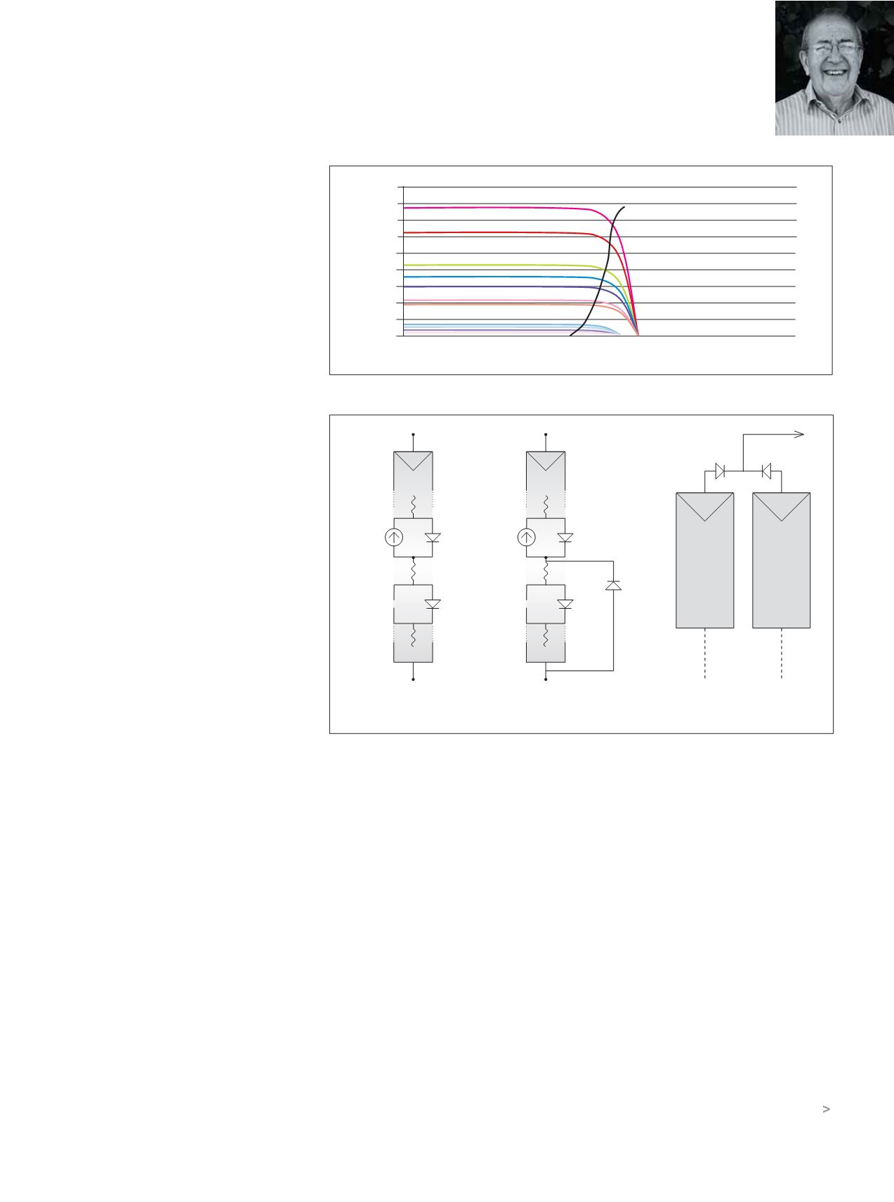
Figures 3a and 3b show two panels in
series, or it could be a larger number (a
‘lumped’ equivalent circuit is shown similar
to Figure 1).
Shading is a problem, and if a cell in a
PV panel is shaded then the series link is
broken and no current can flow. In Figure
3a that’s the situation – no current, whereas
in Figure 3b a bypass diode is fitted across
the two terminals of the shaded panel.
Power and voltage are down, but the
overall system is still working.
For panels in parallel, blocking diodes
(Figure 3c) are used to prevent a panel or
assembly becoming a load rather than a
source of power, e.g. through a short circuit.
PV panel installation guides make the
point that panels of varying characteristics
should not be ‘mixed’. In practice the
advice is to stick to one manufacturer and
type to avoid problems associated with
reliability and power performance.
Installing panels so that they receive
maximum sun is the responsibility of
the system contractor. The website of
the Australian PV Institute is useful for
planning. It allows selection of individual
houses, etc, on maps and the visualisation
of any shadows.
Common sense tells us that the sun
shining normally on a panel will give the
maximum insolation, whereas glancing
sunbeams will yield very little.
In practice, overcast skies make easy
geometrical arguments less relevant.
Further, the lower the sun’s position the
more air there is in the path to absorb
some of the energy.
INVERTERS
There’s a huge number of inverters on
the market, but for most domestic PV
systems the single-phase, transformer-less
type is used.
As a rule, very little technical material is
made available by suppliers. When things
go pear shaped, board replacement is the
only way to get back to a functioning unit.
Transformer-less inverters are much
lighter than those with a 50Hz transformer
grid connection. Technically both do the
same job, but the output transformers
reduce efficiency by several percentage
points. It may not sound much, but it
makes a big difference to the energy
delivered over the life of the PV system.
Both types of inverter systems require a
safety ground connection for the PV panel
array. Transformer-isolated systems can also
have a functional system earth on the PV
panel side – not so transformer-less systems.
There are inverters that connect directly
to the grid like transformer-less systems,
but they have an intermediate high-
frequency transformer between the PV
panel array and the DC link of the inverter.
In this type of inverter the PV array can
have a functional system earth.
Figure 2: Solar Cell I-V curve in varying sunlight.
Figure 3.
0
0.1
0.2
0.3
0.4
0.5
0.6
0.7
0.8
0.045
0.04
0.035
0.03
0.025
0.02
0.015
0.01
0.005
0
INSOLATRON
VOLTS (Single Cell)
3(c) BLOCKING
3(a) BLOCKING SHADE
3(b) BYPASS


