
50 E L EC TR I C AL CONNEC T I ON
AU T UMN 20 1 6
M
aximum demand in Australia
has been growing much more
strongly than aggregate
terawatt-hours, particularly in the
northern states.
Yet even in the south, kVA demand
has become an important consideration
in distribution companies’ capital
expenditure. As a result, consumers
in areas previously not subject to kVA
tariffs are facing substantial increases in
their energy bills.
Electrical contractors willing to take
an interest in this field can make an
economic case for installing power
factor correction gear, and thereby gain
increased business.
This article deals with technical
aspects and some matters relating to
installation and service.
POWER FACTOR
A power factor of 0.9 lagging – not
too shabby, you might think – implies a
phase angle difference between voltage
and current of almost 26°.
In kVA terms there's an 11% increment
compared with kilowatts, and the
possibility of a sharp increase in the
power bill. To correct the power factor
to 1.00 requires almost half the kilowatt
value in kVArs.
In short, that’s where the cost-benefit
calculations come in: weighing up the
cost of correction against potential
savings in electricity.
Correcting the power factor to 0.95
requires about one-seventh of the
kilowatts in kVArs, reducing kVA to 5%
of kilowatts thus minimising the chance
of a bigger power bill.
The power factor in discussion is the
displacement power factor, equal to
the cosine of the phase angle difference
between voltage and the fundamental
50Hz current – ie: cos
φ
where
φ
is the
phase angle.
It’s not the total power factor,
because that takes into account current
harmonics as well. There is some doubt
on the sensitivity of metering in respect
of harmonics in a particular installation.
However, it's a safe assumption that the
kVA (when based on Kilowatts divided
by the displacement power factor) gives
the demand on which the tariffs would
be based.
CORRECTIONEQUIPMENT
With the exception of electronic loads
such as IT power supplies, most loads
draw lagging current.
Correcting kVArs is almost invariably
handled by capacitors, their leading
current offsetting the load current
lagging reactive component.
Commercially available equipment
mostly employs capacitor-based
correction. However static var
compensation equipment is also
available. The latter type uses solid-state
switching to generate anti-phase current.
A note of caution: the different
technologies have advantages and
disadvantages.
Electrical Connection
does
not offer editorial advice. We highlight
matters so that readers can investigate
technical features and, where necessary,
seek independent advice.
Based on the technical literature, it
seems that some static var compensation
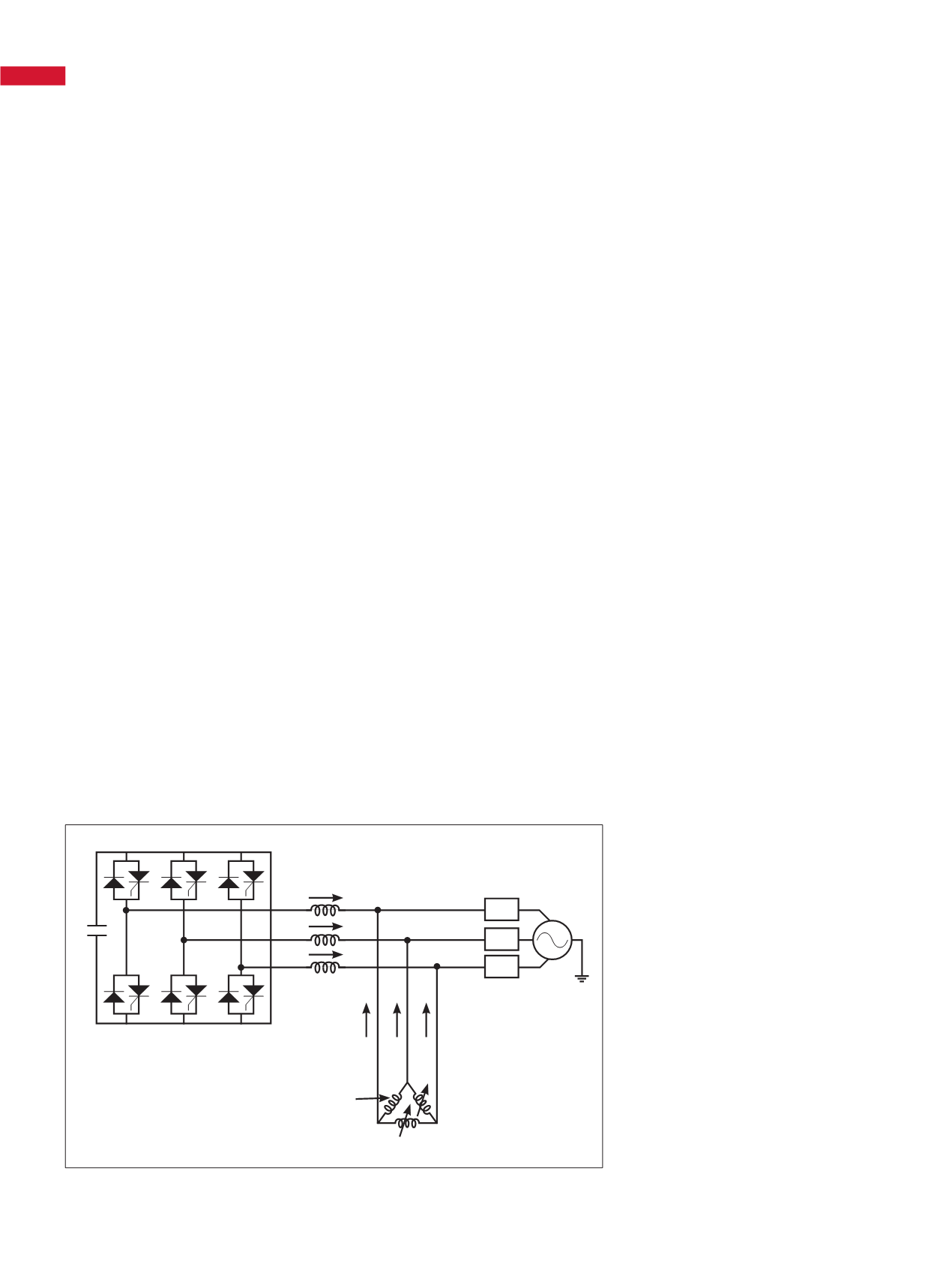
equipment (in particular STATCOM, see
below), offer important advantages.
These include stepless adjustment of
reactive compensation, and leading as
well as lagging power factor correction.
HARMONICS
Office buildings, malls, supermarkets,
etc, have high harmonics generating loads.
There’s a common assumption that
the displacement power factor is close
to unity, but this is not always borne out
by measurements.
QUALITY MATTERS
POWER FACTOR CORRECTION CAN
LEAD TO ADDITIONAL BUSINESS
FOR ELECTRICAL CONTRACTORS.
PHILKREVELD
COVERS THE
CONSIDERATIONS.
Figure 1: Schematic for a STATCOM.
POWER FACTOR
Variable Inductive Load
Source Voltage
V
a
GTO Voltage Source Inverter
iC
a
Z
a
V
b
Z
b
V
c
Z
c
iC
b
I
I
a
I
I
b
iC
c
I
I
c


