
40 E L EC TR I C AL CONNEC T I ON
AU T UMN 20 1 6
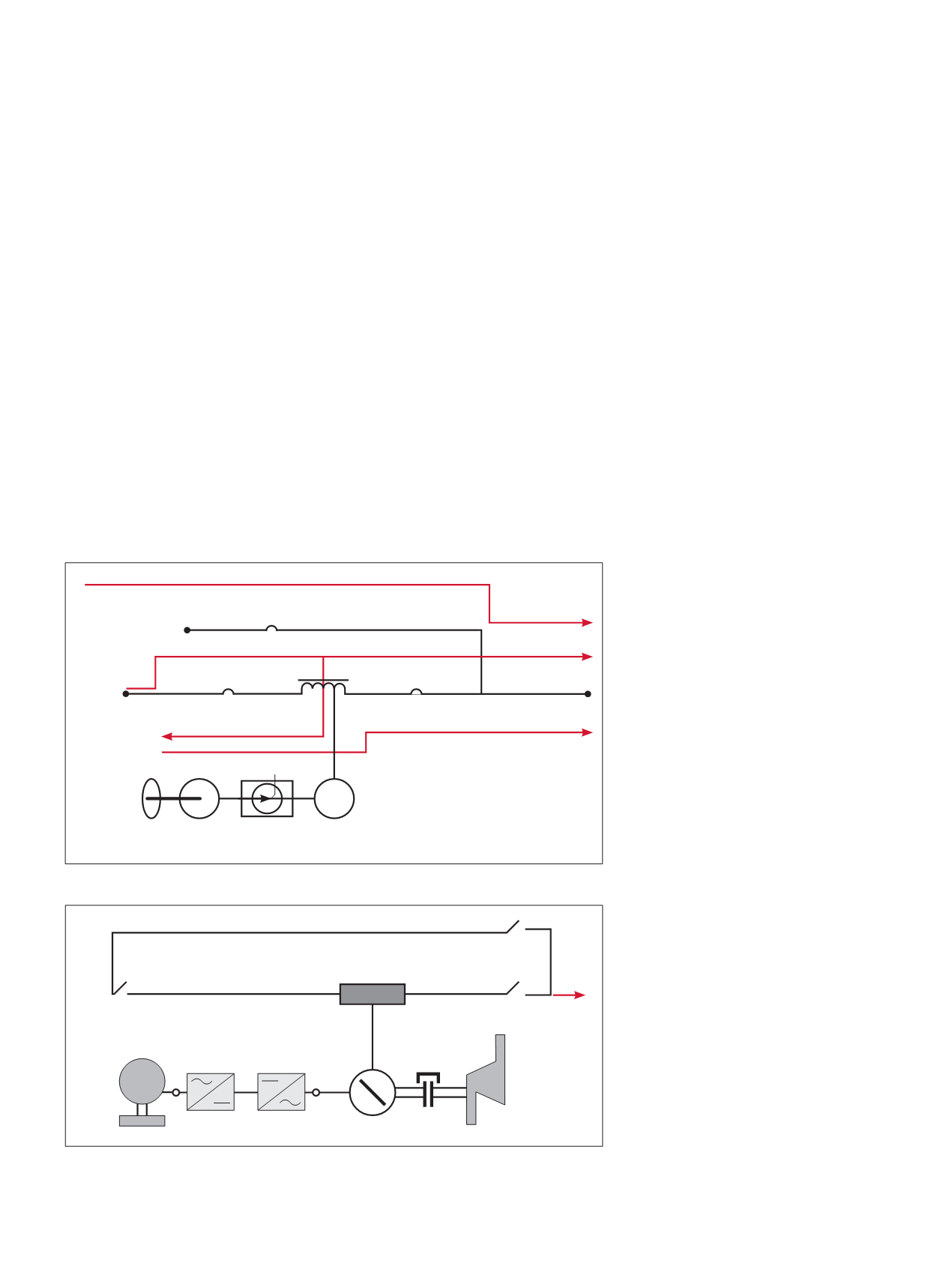
A little more detail is shown in
Figure 4, including the diesel generator
necessary for longer mains failure
periods.
The power converter in Figure 4 looks
a lot like the double conversion system
discussed above. However, the DC link
connecting the two motor generators
has no batteries.
ROTARYANDSTATIC
When UPS systems go beyond 1MW,
the DRUPS technology is more likely to
be chosen.
Some practical considerations have
been mentioned, namely that DRUPS as
a system – without limited-life batteries
– is a more ‘hardened’ system.
A clear advantage of battery storage
is its efficiency compared with flywheel
storage. The trickle charging during
normal operation is about 10% of the
energy required to maintain flywheel
rotational speed.
In cost per kilowatt, high-power
flywheels and lead acid batteries are
of the same order. Lead acid batteries
have a much higher energy storage
density than flywheels.
On the other hand, if chosen for
areas subject to poor power quality,
batteries can be subject to excessive
cycling and their service life will be
reduced.
DRUPS systems (being AC without
sine wave shaping using pulse width
modulation) do not reflect harmonics
into the mains.
POWER FACTOR
We are focusing on displacement
power factor, whereas total power
factor also takes account of harmonic
distortion.
Displacement power factor is a
substantial cost addition to many power
bills. It is therefore of importance to UPS
systems, since we are talking here of
1MW systems and greater.
In the case of DRUPS technology, the
use of synchronous motors provides
power factor adjustment, from lagging
(running as a motor) to leading (running
as a synchronous condenser), so that
maintaining a power factor of unity is
no problem.
DRUPS systems, being AC
throughout, can be affected by the
input capacitance of IT power
supplies, thus exposing standby
generators to leading power factor.
In static UPS systems, AC to DC
converters can have much lower
power factor.
Thyristor converters in normal
full load operation have lagging
power factors, the reason being that
commutation to the off-state can only
happen at zero current. Any inductive
part of the DC link (usually an inductor-
capacitor circuit) will extend the current
on each half cycle.
If insulated gate bipolar transistors
(IGBT) are employed in the AC to DC
conversion, the displacement power
factor is essentially unity because IGBTs
can be gated on and off.
This is a more costly conversion, as
freewheel (snubber) diodes must be
used across the switching transistors
(these conduct the current due to the
collapsing magnetic field of inductors).
Lagging power factors are not
problematic for standby generators
Figure 3: Basic topology of a DRUPS.
Figure 4: DRUPS, power converter, and diesel with coupling to synchronous
motor generator.
Bypass Mode
Normal Mode
Bypass Switch
Bypass AC source
Synchronous
Motor/Generator
Bi-directional
Power Converter
Stored Energy Mode
Mains
Induction
Coupling/
Flywheel
Critical Load
Output disconnect
Input disconnect
Mains
All Load
M
G
G


