Lightning protection for solar installations
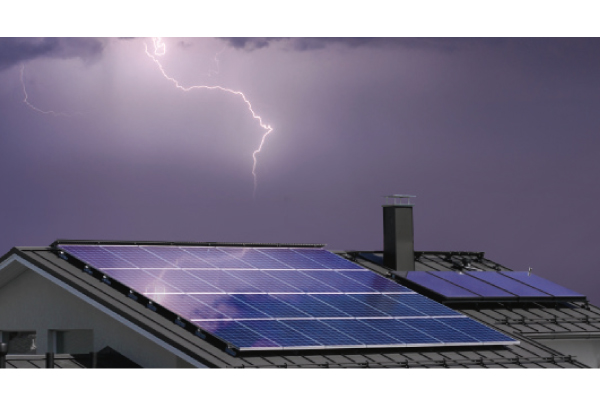 Solar PV systems in susceptible regions should be made safe from nature’s power. Phil Kreveld explains.
Lightning strikes are dangerous, involving currents of up to several hundred thousand amps with rise and decay times of a few microseconds.
Direct strikes causing large, ground step potential differences are hazardous to life and limb, and to equipment.
Apart from direct strikes, induction effects are also hazardous to equipment. However, multiple earth neutral reticulation provides a safeguard but is not enough for a secure ground equipotential for equipment connected over some distance.
ADVERTISEMENT
Lightning occurs in:
- Darwin and the top end generally (more than 80 days a year);
- Cape York Peninsula, Kununurra and Broome (more than 60 days a year);
- South Eastern Queensland (25 days a year);
- South Eastern New South Wales (25 to 40 days a year); and
- Victoria and South Australia (fewer than 10 days a year).
These figures indicate the importance of lightning protection for solar photovoltaic (PV) plant protection in designated areas.
Induction effects
The aim here is to provide some numbers applicable to circuits in the vicinity of lightning strikes.
Assume a bolt with a peak current of 30kA (30 x 103 amps), a rise time of 5.5 microseconds (5.5 x 10⁶ seconds) and a fall time of 75 microseconds.
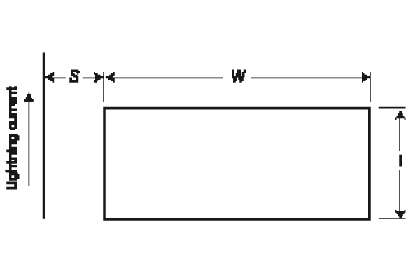 The induced voltage in the loop shown in Figure 1 is of the order of 33,000 volts! Of course, it depends on the orientation of the wire loop, with maximum induction occurring at right angles to magnetic field caused by the lightning bolt.
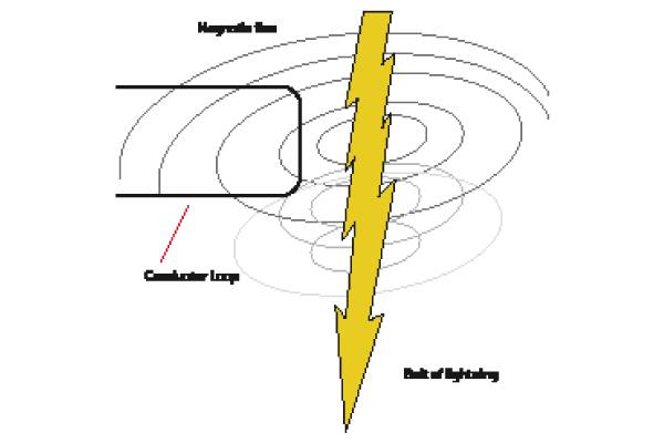
Figure 1: The lightning bolt has a concentric magnetic field which, when linking a nearby wire loop, will cause high voltages to be induced.
Lightning arrestors
The basic task is to provide a high electric field by virtue of a pointed, upward facing part, clear of parts to be protected, to provide a landing place for a lightning bolt.
The very short rise and fall time implies a very high frequency spectrum. Therefore, very low inductance flat ribbons with sufficient cross-sectional area to keep current density to safe limits must provide the path to earth.
Economic considerations may push aside the danger of a direct lightning strike. In commercial installations – particularly those with large roof areas – reliance may be placed on a single arrestor.
Intuitively it seems that the taller a lightning arrestor is, the greater is the ‘shadowed’ or protected area surrounding it.
The challenge in designing protection arises from the inexact nature of protection models. The ‘rolling sphere’ method was developed for substations and is also useful for solar PV installations.
The principle is illustrated in Figure 2. The sphere rolling over an installation should not come into contact with any plant, except those portions where a lightning arrestor is placed or where a strike is not considered dangerous.
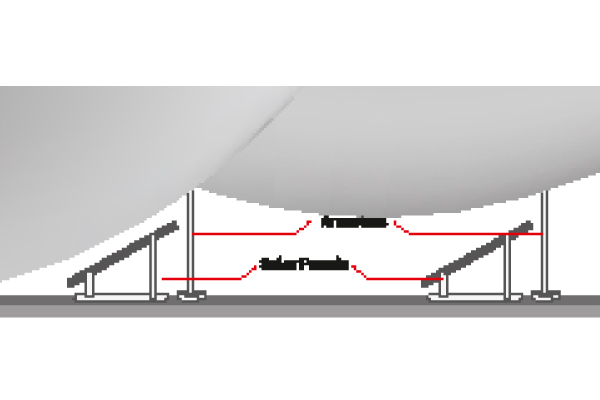
Figure 2: In the rolling sphere method the sphere can make contact with the lightning arrestor, but not with the solar panel.
The rolling sphere method does not guarantee protection. For one thing, its diameter is crucial when considering the shadow area of an arrestor.
In the case of substations, a complicated formula gives the size. For solar PV an arbitrary size is picked, with typical diameters of 20m, 30m and 40m.
A critical aspect in determining the diameter is the ‘withstand voltage’ of insulated plant, that is, the higher the withstand voltage, the larger the diameter of the rolling sphere can be.
Earth resistance is probably too high to avoid dangerous step potential and neutral surges, so for connected buildings an earth mat must be constructed to provide a close to common ground voltage.
Even from several hundred metres away, lightning currents can cause dangerous surge voltages in conductor loops through capacitive, inductive or galvanic coupling.
Large surge voltages can be coupled over a radius of several kilometres. The international lightning protection standard IEC 62305 describes how direct lightning strikes of up to 200kA are safely arrested.
The current is coupled into the earthing system. Due to the voltage drop at the resistor, half of the lightning current is coupled into the internal installation.
The partial lightning current then divides among power lines entering the building (number of cores of power line entering building), and about 5% enters data cables, as shown in Figure 3.
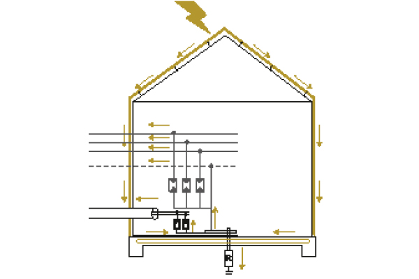
Figure 3: The loop area of panel wiring must be minimised to avoid excessive induction voltages. Figure 3b illustrates the use of coaxial cable to avoid inductive loops. Figure 3c indicates the correct method for installing surge protection devices.
Layout of panel wiring
To minimise induction effects, cable lengths must be minimal. On the DC side of a solar PV system the cable length of the positive and negative terminals can be reduced by twisting the leads together to minimise the cable loop surface.
On the AC side, the cable length of the protective earth, phase and neutral conductors can be reduced by twisting them together to avoid large loops.
To have an effective routing precaution, the loop area (DC side connection and AC side power line) must not exceed 0.5m2, in accordance with the Standard IEC 62305-2 [4].
Unfortunately, it is not easy to achieve this value, mainly because the junction box of each photovoltaic module has connection cables (positive and negative terminals) of about 1m spaced 10cm apart.
The formulas for evaluating induced voltage are provided in annex A of Standard IEC 62305-4 [6]. It is possible to calculate the number of modules connected in series/parallel forming a loop area sufficient for an induced voltage greater than 1.5kV due to a nearby flash (250m away with a maximum current of 30kA).
A photovoltaic array field with fewer than 200 modules – and total power less than 40kW peak obtained by assuming 200W peak per module – should not have any problems.
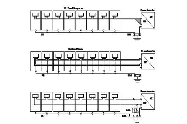
Figure 4a: The loop area of panel wiring must be minimised to avoid excessive induction voltages. Figure 4b illustrates the use of coaxial cable to avoid inductive loops. Figure 4c indicates the correct method for installing surge protection devices.
Surge suppressors
As shown in Figure 4, these must be installed on the DC link side of the inverter and at the point of coupling (the AC side of the switchboard).
The metal oxide varistor (MOV) is probably the most popular clamping device used for transient suppression.
MOVs consist of millions of tiny semiconductor junctions (PN junctions) that act as diodes with larger forward voltages. A common material for MOVs is a granular form of zinc oxide sandwiched between several parallel electrodes.
The MOV is inherently suitable for AC voltages, as the diodes are disposed in all directions. As the voltage across the MOV rises, more and more diodes turn on. The result is, in effect, a non-linear resistance that reduces incrementally with increased voltage.
This is precisely the effect needed for clamping excessive voltages on the device being protected.
A clamping function requires effective voltage division. At line voltage the MOV is essentially an open circuit, but as the voltage rises the differential resistance DR – which is equal to DV/DI – decreases.
Provided the impedance of the upstream circuit to which the MOV is connected is higher than DR, voltage division will lower the transient voltage. However, MOVs have a high let-through voltage. That is to say, the voltage across the device continues to rise with input voltage, albeit at a much reduced rate because of the low DR.
On the other hand, silicon avalanche diodes (SADs) have a sharply defined clamping voltage (being the point where the reverse biased diode junction breaks into avalanche mode with reverse leakage current suddenly increasing by orders of magnitude).
The DR of the device is then a virtual dead short, and the voltage is clamped at the avalanche point (no let-through voltage effects).
Compared with MOVs, SADs have a much reduced energy dissipation capacity and are therefore not usually employed on power circuits.
So far, voltage transients have been considered as time-dependent phenomena. They can also be thought of in terms of frequency spectra. The faster the rise time of an impulse, the broader is its frequency spectrum.
Filters constructed from inductors, capacitors and resistors can be very effective transient suppressors, as mentioned earlier. The low-pass filter, which can take several forms, represents the standard method of reducing the slew rate of fast transients.
The feed-through capacitor, combined with the self-inductance of the leads connected to it, forms a low-impedance path to earth for the high-frequency components (those associated with the fast rise time of the transient).
The need for specialists
Lightning protection is specialised branch of electrical engineering. For commercial and industrial installations in areas of high lightning incidence, specialists should be consulted and preferably engaged to design and implement protection systems.
-
ADVERTISEMENT
-
ADVERTISEMENT

