Leading the charge
Battery testing and charging for substations and electric traction can be challenging. Phil Kreveld delves into the detail.
The important difference between charging for substations or for electric traction is time.
ADVERTISEMENT
In many traction applications, recharging a battery is compared to filling up quickly with combustible fuel; in substations, time is not an issue.
Lead-acid batteries are used in both areas, but lithium-ion batteries by virtue of their superior energy density are highly desirable for vehicles requiring an extended operating range.
However, the complexity of multi-cell battery packs takes away some of that inherent advantage. When it comes to testing, lithium-ion makes sense for stationary applications but is complicated for vehicles.
Substations
Without emergency power, substations would be severely compromised.
Protective relays may require emergency electrical supply in case of blackouts, but that is low-power stuff. Operating isolating switches and circuit breaker trip coils requires more power.
In some cases emergency power is necessary for motors that rewind breaker spring sets, and other tasks requiring AC voltage. For the latter, uninterruptible power supplies are used, and these also require battery banks. High-voltage substations often have primary and back-up battery supplies.
Battery testing at regular intervals is a given, and incoming inspection is also necessary. However, there is also a need for battery monitoring to provide a continual check. Battery monitoring relies on cell voltage, string voltage, string current and battery impedance measurements. The latter type of testing is particularly useful for UPS battery banks.
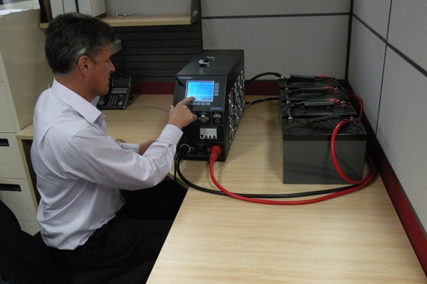
Figure 1, above, illustrates a discharge tester suitable for lead-acid cells. The apparatus allows for constant current, constant resistance and constant power discharge. Individual battery voltage is monitored during the discharge.
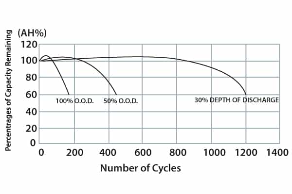 Figure 2. The state of charge of VLRA batteries being checked on an IDCE840 battery tester, Courtesy of Power Parameters.
The batteries used in substations are flooded cell (VLA), valve regulated lead-acid (VRLA), vented nickel cadmium (Ni-Cd), and recombinant nickel cadmium (RNi-Cd). The testing regimes have to be appropriate to battery capacity characteristics.
The lead-acid VLA and VRLA require frequent testing by the time 80% of capacity is reached. Thereafter the testing frequency should be increased to yearly intervals.
With the Ni-Cd batteries, the test frequency should be at five-year intervals – and when at 90% of rated capacity it should be annual. The thing to realise is that rated life is a bit like how long a piece of string is. Figure 2 makes that plain.
Regardless of the amp/hour capacity of a particular battery, the more discharge cycles it is subject to the shorter its lifespan will be. Battery tests, if they include a 100% depth of discharge (DOD) will, as the graph illustrates, shorten life the most.
Battery maintenance practice should include amp/hour data collection. (This is not a DOD statistic, since float charging takes place – or usually can be expected between discharge events.)
The VRLA battery is the most popular type in substations. Its one-way valve can, in cases of over-charging, vent gases (hydrogen and oxygen) but that’s not what should usually take place.
In VLA (flooded cell) batteries the creation of hydrogen gas, H2 and oxygen radicals (1/2-O2) causes water loss in the electrolyte, and a reduction in the electrolyte specific gravity resulting a decrease in cell open-circuit voltage.
In VRLA batteries the electrolyte is immobilised by means of a porous separator between the positive plate (lead oxide) and the negative plate (lead, in sponge form). The separator is an absorbent glass mat (AGM) trapping the oxygen – or, better put, making the gas diffuse slowly to the negative plate where lead oxide is slowly formed during the battery discharge.
Despite the inherent ruggedness of VRLA batteries, over-charging will lead to oxygen generation in excess of the AGM’s ability to trap the gas, and out-gassing will occur via the one-way valve. If the over-charging continues, a premature drying out will occur with a permanent loss in capacity. The recharging process is therefore very important.
Given a battery’s capacity, C, in amp-hours, the total charge that needs to be replenished in order to restore its capacity is of the order of 1.10C. There’s no such thing as a free lunch, and more energy needs to be put in than will be extracted during the discharge.
The energy loss in a battery during charging is I2rb where I is charging current and rb, the internal resistance.
The specifics of battery charger operation are crucial for substations. They form part of the general DC power requirements during normal operation, thus requiring some special circuit considerations.
Under normal operation only the charge loss due to internal charge leakage needs to be made up. The process is variously referred to as trickle charging or float charging. Irrespective of the semantics, making up for more than the charge lost will shorten battery life in the long term.
Charging current Ic is equal to the difference in charger voltage and cell voltage divided by the total resistance, which takes into account any current-regulating resistance, circuit resistance and cell internal resistance.
The higher the charging rate, the more quickly cell voltage rises, necessitating a further increase in charging current and a rise in cell temperature.
Figure 3 shows the process for a 5C charging rate, that is, a 200A-h battery would be bulk charged initially at 40A. As the graphs show, temperature rises slowly initially but then takes on an exponential slope. It is clear that to prevent excessive temperature the rate of charge should be decreased as the battery approaches 80% charge.
Battery chargers
Before looking at substation DC power reticulation, charging circuits should be examined.
A constant voltage charger should in the first place have an output above the highest open circuit cell voltage. It has the advantage that current decreases as the battery gains charge, but its charging rate will be considerably slower than with a constant current source.
However, such a charger should have a way of stepping the charger current down as the battery gains charge.
For substation duty some form of charger temperature compensation is important. This also applies to the battery bank room, which ideally should be held within a tight band of 15-25°C.
Temperature has a substantial effect on float current provided by a constant voltage source. The float current must roughly double for each 10°C rise in cell temperature.
Increased heating of cells and reduced heat flow from batteries increases the risk of thermal runaway. Higher ambient temperatures are obviously implicated here.
This effect is particularly observed in VRLA batteries rather than in vented (flooded) cells, because the formation of oxygen is an exothermic reaction. In the case of sealed VRLA batteries, the heating effect and joule losses can add up very quickly to higher temperatures.
The ability to de-sulphate the negative plate, which gains a layer of lead sulphate as the battery discharges, is an advantage. Some chargers incorporate a de-sulphating pulse, although its mechanism is not well understood, and some chargers use a form of pulse width modulation to control the charging process.
This latter method combines the advantage of constant current charging with the inbuilt feature of tapering current of constant voltage chargers. Using pulse width modulation, the current pulse width is reduced by means of an algorithm and/or a suitable feedback mechanism based on cell voltage.
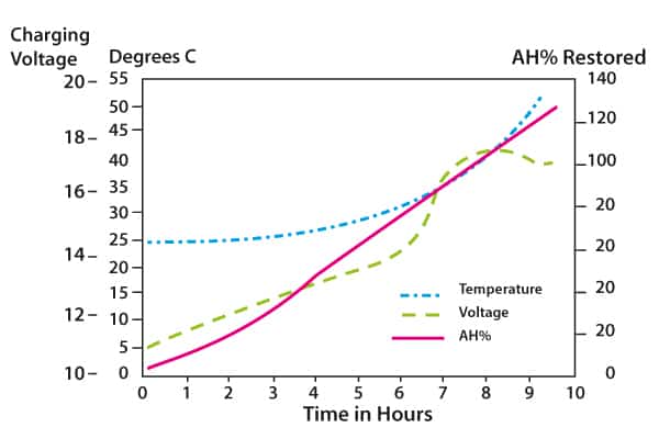 Figure 3. Constant current charging of a VRLA battery
DC circuits
Substation DC circuits vary, but there are some generalities as shown in Figure 4.
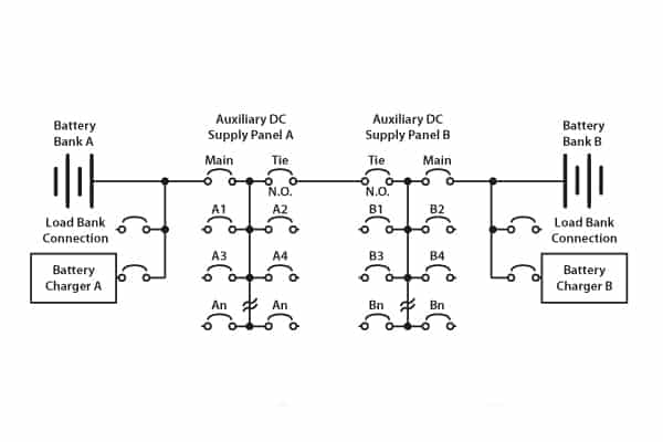 Figure 4. Typical redundant layout for a substation
In the dual-battery system as shown, the chargers A and B function not only to trickle charge the two banks but also to supply the various DC circuits: that is, DC coils for circuit breakers, DC motors for energising trip springs, and protection relays.
Electro-mechanical versions are powered by potential and current transformers. However, many are now electronic, using microprocessors and requiring a constant DC power supply – or at least as an alternative if the normal energising is via a switch mode power supply.
Although we are focusing on batteries, charger functions should also be checked. The challenge in the above arrangement is to provide stable voltage under normal operation and appropriate voltage for the float charging process.
Furthermore, account must be taken of operating with parallel battery strings, and protection – for example, ensuring that one battery’s shorting does not affect the others.
A very important parameter in chargers is ripple. The AC ripple sitting on top of the DC current component is deleterious to batteries. It may not be an intuitive reaction if one looks at a sine wave about a DC level. There are as many peaks going higher than the DC value as there are troughs below.
That might lead you to conclude that the net result is simply the effect of the DC component only. However this is not the case. The actual rms (heating value) is given by the formula:
In the formula, Ieff is the effective charging current, IDC is the DC component, and IAC, the AC component.
In substation maintenance, testing ripple is crucial. If the voltage ripple is sufficiently large during negative excursions to be under the open circuit cell voltage, discharges will take place.
The current ripple component provides additional heating. For minimal heating influence on the battery banks, ripple voltage should be well under 2% peak to peak, and under 4% peak to peak if discharge effects are to be avoided.
Although DC circuits in substations vary widely, there are several aspects that must be taken account of. The first one being protection against battery cell shorts.
The principle of the circuit is shown in Figure 5, in which two parallel strings are shown by way of example. The circuit would also apply to a large number of parallel strings.
The underlying assumption is that, apart from forward voltage drops in the steering diodes, the load and the batteries can use the same voltage. Yet that is often not the case.
If a battery cell or cells shorts in the second string then diode D3 will be reverse biased. Charging of the string can still take place via D4, but no current can be drawn from the first string.
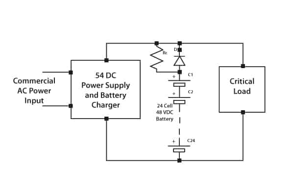 Figure 5 Protection of parallel strings
In many applications, a float charge service is required whilst supplying the critical load during normal operation. In this instance charging current must be limited. The circuit shown in Figure 6 fulfils this function by means of a current-limiting resistor. The battery string discharges via the diode when main power fails.
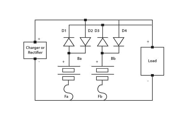 Figure 6. Parallel supply of load and float charge
Substation power supplies incorporating charging functions can be provided with a number of important features, including high and low voltage alarms, AC and DC output status, ripple alarm and battery ground detection for floating DC supplies.
A battery ground-detection system uses a resistive voltage divider so that positive and negative terminals of the battery bank maintain equal magnitude voltage values with respect to ground.
The resistive divider has an added benefit, namely to function as a bleed-off for any capacitively coupled voltages that might interfere with the operation of protective relays.
As a further improvement, battery monitoring can be installed. This is generally based on measuring two important parameters: cell voltage and impedance.
One method involves the injection of a very small high-frequency current and measurement of the voltage drop across the cell. Battery impedance coupled with open circuit cell voltage provides a very good ‘state of health’ for batteries.
Traction
Smaller vehicles are the focus here, including forklifts, ground equipment for airports, and short-range transport.
VLRA batteries are prominent, but so are lithium batteries because of their high ratios of energy to weight. More varied than for lead-acid types, the chemistry for lithium batteries is outlined below:
The cathode in such batteries is a lithiated metal oxide, and the anode is made of graphitic carbon with a layered structure. The electrolyte is made up of lithium salts dissolved in organic carbonates.
When the battery is being charged, lithium atoms in the cathode become ions and migrate through the electrolyte towards the carbon anode where they combine with external electrons and are deposited between carbon layers as lithium atoms. The process is reversed during discharge.
In outline, efficiency is close to 100% and life span approaches 3000 cycles at 80% depth of discharge. Operating temperature ranges from –30°C to 60°C, energy density is 90-190Wh/kg and self-discharge is about 1% per month. However, the higher cost is due to special packaging needs and internal over-charge protection.
On the basis of amp-hour ratings, the cost comparison with VRLA batteries is unfavourable. Yet when depth of discharge is considered the picture changes.
It is generally accepted that the most economic and practical DOD for a VRLA-AGM battery is 50%. For lithium-iron-phosphate (LiFePO4 or LFP) – the safest of the mainstream Li-ion battery types – 80% DOD is used.
Charging
The main aim in charging lithium batteries is temperature control to minimise the effect of lithium plating of the anode.
Much depends on the physical design. A thin, highly porous anode works best for very fast charging – rates as high as 1C.
Undercharged lithium batteries lose capacity permanently, requiring special precautions on recharge circuits. Lithium-ion batteries cannot absorb overcharge. When they are fully charged, the charge current must be cut off. A continuous trickle charge would cause plating of metallic lithium and would compromise safety.
Over time, the open circuit voltage will settle to between 3.70V and 3.90V per cell. A typical charge profile for a single cell is shown in Figure 7.
For a partly discharged cell, a pre-charge precedes the transition to constant current charging. Monitoring of cell voltage is essential, in order to switch over at the correct voltage to constant voltage charging.
When dealing with battery packs, equalisation of voltage between the cells is very important.
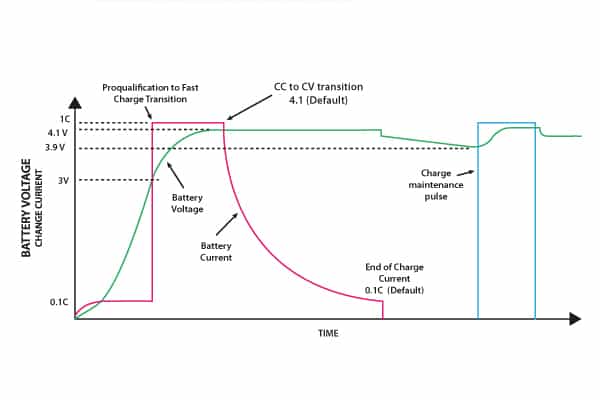 Figure 7. Charging profile for a Li-ion cell
Unlike lead acid batteries, which can equalise simply through out-gassing, there is no natural equalisation mechanism for lithium batteries.
Their employment in strings and parallel strings requires that unequal cell voltages be eliminated. Methods for achieving this include flying capacitor circuits and many others. The flying capacitor circuit is illustrated in Figure 8.
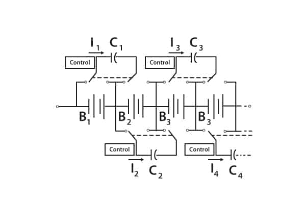 Figure 8. Voltage equalisation with flying capacitor circuit
Capacitors constantly switch between cells, thereby swapping charge from higher-charged cells to lower-charged cells. Each capacitor requires simple controls to activate the switches.
There are other methods, such as the switched transformer method.
Figure 9 shows the stack voltage being chopped by the transistor-control circuit, which also monitors individual cells, and the rectified voltage from the transformer secondary replenishes individual cells.
 Figure 9. Switched transformer voltage equalisation
As will be evident, the voltage equalisation circuitry as described can form the basis of a battery monitoring system. This has been used, possibly experimentally, in some commercial vehicles.
-
ADVERTISEMENT
-
ADVERTISEMENT

