


 30 / 116

3 0
E L E CT R I C AL CONNE CT I ON
AUTUMN 2 01 5
The first type has a large series choke in
the DC link storing energy proportional to
(current)
2
, and the second has capacitors
storing energy proportional to (voltage)
2
.
The voltage inverter is most frequently
encountered and generally supplies unity
power factor energy.
To control power factor, the phase angle
of the current supplied to the grid must
be compared with grid voltage, hence
the usefulness of a current-based inverter.
However by putting reactive impedance
between the voltage inverter and grid
connection point, a quasi-current generator
has been produced and phase comparison
between current and voltage can take place.
Domestic PV systems use maximum
power point tracking (MPPT) on the DC side.
Irrespective of the algorithm (although it is
often the ‘hill climb’ one), there is a DC to DC
converter supplying the DC link of the inverter.
The inverter, as a rule, has a lower rating
than the solar panel so that the system has
adequate power output control. The inverter
pushes out unity power factor energy and,
as already stated, therein lies a problem for
power distributors.
A better approach is to more closely
match the inverter to the PV panel by
making the power point tracking operate
directly on the inverter rather than on the
DC link. This approach is available on some
three-phase inverters. In one such system,
the power available is – as would be the
case in DC to DC converter systems – the
product of panel voltage and current.
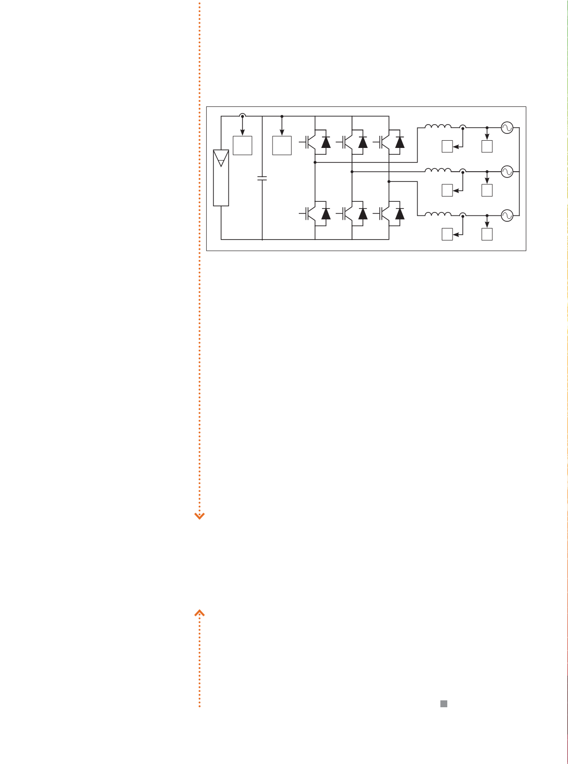
Using fuzzy logic semantic rules in
conjunction with ‘hill climb’, a PI controller
compares actual DC bus voltage and the
reference generated by the MPPT and
provides an active current reference. This
reference is ‘attached’ to the grid voltage
phasors and is part of a d-q transformation
(Park transformation), similar to that used in
active harmonic filters.
The inverse of the transformation
generates the required phase current. The
feedback mechanism is shown in Figure 2.
How serious is the feed-in problem
likely to become? It’s not in our brief to
make forecasts.
The Clean Energy Council provides list of
compliant inverters suitable for renewable
energy certificates (RECs). Mainly, inverters
have to comply with AS4777. For systems
between 30kW and 200kW, compliance with
IEC62109.1 or IEC 62109.2 is specified.
The index for the Standards reveals
nothing on power factor. For power above
200kW, the above IEC Standards or VDE AR-
N4104 is specified.
The German specification has sections
pertaining to influence on the grid, and
these are specified by VDE AR-N4105 in
regard to frequency stability – including
photovoltaic installations.
The Standard says they need not be
completely disconnected from the grid on
reaching an over-frequency of 50.2Hz, but
there should be a smooth transitional zone
between 50.2Hz and 51.5 Hz, within which
the installation may continue to feed in
power at a reduced capacity.
This new application guide also affects
existing plants with outputs of more than
10kWpeak, and they need to be upgraded
accordingly. We lack these requirements
here, but individual distribution authorities (in
particular in South Australia) enforce their own
rules and provide for additional protection –
for example, anti-islanding relays and phase
loss relays in the sub-distribution network.
There may well be an increase in multi-
mode inverters in the near future. Rather
than ceasing operation when the upper
voltage limit is reached, the control circuitry
reduces energy production.
However, one unavoidable scenario is
the presence of multiple inverters on the
same sub-distribution circuit. Depending
on the impedance of sections between the
inverters, the practical effect may well be that
‘imposed’ voltage knocks out other inverters.
It seems some spade work must be
done by supply authorities and the solar
industry, irrespective of RET outcomes,
as the penetration of ‘distributed
generation’ grows.
There may well be an increase
in multimode inverters — they
reduce reduce power when the
upper voltage limit is reached.
Figure 2: Inverter with powerfactor adjustment capability.
E
a
1
a
E
c
1
c
E
b
1
b
U
dc
I
pv