Solar Smarts: Getting the most out of each ray
In light of solar panels continual growth across the country, Phil Kreveld writes about how to optimise their efficiency, getting the most out of what the sun gives us.
There is every prospect that reliability and efficiency of solar systems connected to the low voltage distribution networks will grow in importance as our reliance on distributed energy resources (DER) increases.
ADVERTISEMENT
This will result in the industry’s efforts to optimise efficiency for new installations, and that existing ones do not degrade in performance. For the installers of solar systems there is the opportunity to add value to their services as well as grow their maintenance business through regularly planned inspections.
The intensity of the sun (insolation), the latitude and altitude of the location, the zenith angle of the sun, the orientation of the solar panels (horizontal or inclined and angle relative to noonday azimuth), the level of light diffusion, maximum daylight temperature and environmental conditions of humidity, salinity and so on, all affect the ultimate performance of a solar installation.
In the practical world of solar installations for domestic, commercial and industrial purposes, not much thought is given to these factors. It’s more a matter of the installation’s address and available roof area.
Solar panels with nominal performance of around 50W per panel and their total number determine the nominal energy to be harvested. This doesn’t imply a cavalier attitude of solar system installers; rather that installations, other than solar farms, are more a matter of selection of the panels, junction boxed, isolators and inverters.
Evaluating the overall energy conversion efficiency of a solar installation and increasing its performance can be a straightforward matter involving nothing more than cleaning the solar panels with a soapy water solution. Energy harvested by an installation also would appear to be restricted by the roof size and orientation of its surfaces. It’s because of these rather common-sense restrictions that energy conversion is ‘what it is’.
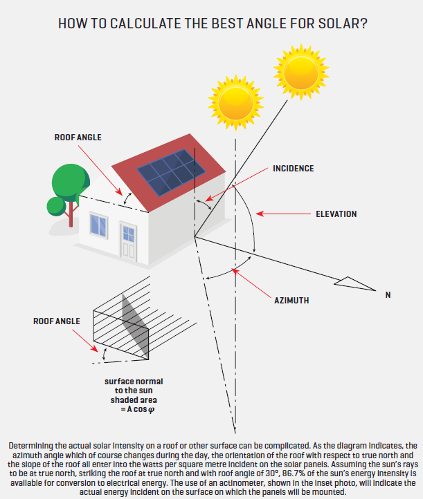
However, without ‘blinding ourselves with science’, for a prospective installation a short survey using an actinometer and datalogger on the available east and west facing surfaces of a roof will indicate best available options for siting solar panels.
An actinometer measures the energy intensity at the surface on which it is mounted, whether inclined, vertical or horizontal. This sort of gear can be hired quite economically, and therefore adding very little to the cost of an installation. It can also help solve why, for some reason or other, an existing solar system doesn’t perform like it did in earlier times.
Of course, the sun’s trajectory hasn’t changed, nor the orientation of the roof surfaces but comparing measurements at installation times with those obtained later will reveal changes in panel efficiencies due to degradation, for example, saline atmosphere induced leakage current.
Working out in theory what the ideal performance of solar system should be is not recommended. There are links (one being cableizer.com/tools/solar_radiation/) which do all the calculations for you and provides the maximum insolation (energy intensity in watts per square metre) for vertical and horizontally oriented surfaces. Being able to explain the differences to an owner now in Melbourne and previously in the Riverina adds to professionalism of installers and designers of solar systems.
Solar system design rules are well covered elsewhere but even so, a few important principles are discussed because as revealed by the Facebook group ‘Crap Solar’ there are many unprofessional installations around.
A contractor looking for additional business, be it service or ‘re-engineering’ might be interested in reviewing solar systems offering opportunities for improvement. In the accompanying article (also in this magazine), Solar Installation Maintenance, factors affecting the current output of solar panels and the individual strings and finally of the parallel combination of strings were discussed as well as maximum power point.
Note that these maximum power points often differ significantly between each other. In figure 1, the familiar individual solar cell characteristic is shown as current versus voltage.
It can similarly be applied to a panel or to a string. Insolation levels determine the current and less so the open circuit voltage. The maximum power point is where we should be operating—but here’s the surprising bit; there is no easy way of checking whether the system is or is not at its maximum power point.
For example, partially shaded strings in parallel with those that are in bright sunlight, will lower the maximum power point. In split systems, for example with east and west facing panels, even though an inverter with two maximum power point trackers (MPPT) is installed, maximum power point is compromised because of unequal panel string performance on the two sections of the roof.
From an inspection aspect, there is little point in testing the MPPTs as they are an integral part of the inverter. At first blush, it has to be assumed they are, circuit-wise doing their job. An explanation of the principles of operation will be helpful though as without having to delve into the circuitry, it will aid investigative procedures to improve performance of the solar system as a whole. In figure 2, the power output of an unshaded panel is shown for a single level of insolation.
Voltage and current of the external load at first rise linearly, as would be expected from a pure current source but that’s a theoretical concept. Maximum power transfer from a source to a load occurs when the source and load impedance are equal. A ‘real life’ current source such as a solar panel has a shunt resistance and the maximum power is delivered to the load when both are matched in value. Although from a theory aspect, a helpful concept, the operation of maximum power point trackers doesn’t bear any similarity as they are tied to the operation of the inverters.
Most inverters in domestic installations have their power fed by buck converters, which reduce the panel voltage to one just exceeding the peak AC line voltage.
That small difference in voltage has to be sufficient for the inverters to push out current for the domestic load and power export. The inverter is in electrical terms a voltage fed, current source. The buck converter is basically a pulsed DC to DC voltage transformer, with the pulse frequency determined by the operation of the inverter and the step-down ratio determined by the on-off ratio of a switching transistor.
The input voltage, i.e. the panel voltage is determined by a separate pulsed circuit. One, often used, is the so called ‘hill climb’, which is best thought of as beginning sampling of the panel voltage and current at the maximum value (i.e. open circuit voltage), stepwise, reducing voltage and at each step calculating the power (voltage multiplied by current). The process as described will yield increasing power until the peak (as shown in figure 2) is reached, whereafter further voltage reduction steps result in smaller values of power. The process is a dynamic one, best thought of as ‘hovering’ around the peak—or peaks as multiple peaks can occur in partially shaded panels.
From the foregoing it is clear that maximum power output for a solar system with two sets of panels relies on the same open circuit voltage, i.e. identical number of similar performance panels per string and shading, if present. The former is a matter of correct design (and for service check-up, certainly something that should be checked as some panels may have developed malfunctions). The latter point, shading is difficult to control but here may be some obvious fixes such as removing obstructions such as nearby tree branches.
Hybrid solar systems interpose the storage battery between the maximum power point tracker and inverters so that the battery has to be matched in voltage to the peak AC line voltage. Although in hybrid systems the battery voltage is below that of the panel open circuit voltage, and therefore cannot discharge through panels, the use of blocking diodes in panel string assemblies is still recommended as otherwise healthy strings can power faulty ones and diminish power available to the inverter.
Inverter malfunctions are best left to be fixed by suppliers or authorised service agents. Even so where a visual inspection of the ‘innards’ is possible, the DC link capacitor should be inspected because it is in many ways the most vital component and subject to failure because of the continual charge-discharge cycles. It is an integral part of the buck converter of the maximum power point tracker, which as already explained relies on a gated transistor, controlling the energy stored in the magnetic field of an inductor coil (taking current from the solar array) and dumping it into the capacitor. The capacitor is the voltage source for the inverter, dropping voltage as current is drawn from it, its charge-discharge cycle determined by the switching frequency (of the order of 2 to 5kHz) of the inverter.
Regular inspections of domestic solar installations are still a novelty but that ought not to be the case given the importance of their energy contributions in Australia’s electrical grids. A relatively simple test that can be conducted is to use a DC clamp meter at the combiner box to measure voltage and current and to measure AC current and grid voltage at the inverter. For a properly functioning solar system, irrespective of the time of day or insolation, the efficiency (ratio or rms current times voltage divided by the dc current times voltage, should be in the nineties percentage-wise. If not, there’s a serious problem. Remember that the DC measurements you are making at the combiner box are basically the inputs to the maximum power point tracker(s) and therefore do not indicate how well the tracking is performing vis-à-vis the power available from the panels (the DC voltage and current being what the tracker has selected, whether the actual maximum power point has been selected or not). Determining the maximum power performance of the panels requires the use of a curve tracer providing a trace of a string(s) similar to figure 2.
Lastly there is the vexing problem of line voltage for many solar installations. Vexing, because virtually everywhere distribution voltage has been on the rise, and solar inverters by virtue of their anti-islanding protection cease operation above 254V line to neutral (or below 207V). There are devices which can ‘insulate’ the inverter by the use of a solid-state transformer, keeping the voltage at 230 to 240V at the inverter terminals. Whether this conflicts with anti-islanding requirements of distribution networks are not clear. Although may if not most smart meters do not only measure power and energy, but they also measure voltage but voltage data is not readily available. The rental of a line voltage logger is recommended for underperforming installations which do not exhibit any problems but where kilowatt-hour output is suspiciously low. Some distribution networks will respond by setting local transformer taps lower.
-
ADVERTISEMENT
-
ADVERTISEMENT


