PID loop tuning is our profession
 Glen McMurtrie explains how to stop worrying and learn to love PID loop tuning.
In a previous issue we discussed the terms proportional, integral and derivative (PID) and how they relate to continuous process control. This time we focus on tuning methods for implementing PID on your controller, with emphasis on the physical characteristics of a system.
The golden rule of Instrumentation is know your process. It is pointless trying to tune a controller if you have no idea what magnitude of change to expect if:
ADVERTISEMENT
- you manually drive an output value; or
- transmitters and valves are not calibrated and in good working order.
Take time to walk around the plant. Is it of large capacitance where changes happen slowly or is it small and dynamic with rapidly changing variables? Pay attention to whether valves open or close with increasing signal, and read the piping and instrument diagrams. Trust me, this saves a lot of time.
Put simply, when you tune a PID controller you are matching its gain (P) and time functions (ID) to a process. Your objective should be to achieve stable control of the process variable with a fast response to set point changes and upsets.
However, different processes exhibit different kinds of behaviour.
Take a flow transmitter and valve installed in a pipe. If the valve is manually opened or closed a certain percentage, the rate of flow measured by the transmitter will change in a certain percentage and settle on a new value – this is a self-regulating process. Now consider a level transmitter installed on a tank, and a valve on a water line into the tank. If the level is constant – that is, inflow equals outflow – and the valve is opened by a certain percentage, then the level will start to rise and will continue to rise at a certain rate.
This is known as an integrating process.
Generally speaking, self-regulating processes require quite a lot of integral action to continually drive the output to its required value after the input value has stabilised. Integrating processes rely primarily on proportional gain to make changes in output as the input changes.
Consider our examples of the flow line and tank level. If the flow being measured in the line suddenly increases 10% we wouldn’t want that valve suddenly increasing 10% or more – we would want to ramp the valve in the required direction to reduce the flow back to set point.
However, if the level in the tank increases 10% we would want that valve on the incoming line to really do something – chances are, to move 10% or more. Remember, these are very general analogies – there are well-known procedures for tuning a process control loop. One very coveted method was devised by two engineers in the United States in 1942 named Ziegler and Nichols.
They wrote a paper titled Optimum settings for automatic controllers, and much of it is still relevant today. Their tuning method requires the controller to be put in manual mode so that the operator can change output values. When an output value is changed, we record the time until the input value starts to change (dead time) and how much the input value changes in a certain time.
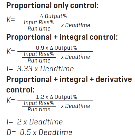
Using these simple formulas we can determine approximate values of P, PI or PID depending on which control combination you think is best suited to the process (see previous issue’s article for a detailed explanation of PID control).

K = proportional gain ( =Proportional Band%)
I = integral time in seconds
D = derivative time in seconds
Note that for the ‘P’ function most American controllers are proportional gain (Allen Bradley, Emerson) and the rest of the world proportional band % (Yokogawa, Siemens).
Don’t be too put off if this all seems daunting. PID loop tuning is a skill that takes a long time to develop. I highly recommend downloading one of the many free loop tuning programs to practise on before you attempt to tune any live process.
Below I will run through an example to follow using P+I control that usually suffices on most processes.
Let’s use the tank example mentioned earlier. The controller is placed in manual and the output to the valve moved 10%, causing an increase of inlet flow. Twenty seconds later the input level value on the controller starts to rise.
(∆ Output% = 10% Deadtime = 20 sec). We then start timing the rise of level and we notice it has increased 5% in 60 seconds. (Input rise =5% Run time = 60sec).
Using the formula for P+I we should see:

therefore, K=5.4
Or, for proportional band, PB= 100/54, therefore, PB=18.52%
Integral time, I=3.33 x 20 , therefore I=66.6 seconds
We can then enter these values into our controller and place in automatic mode. Observe the process response at first and, if steady, make a set point change. It may not be perfect but at least we have starting values from which we can fine tune.
In this game practice really does make perfect.
-
ADVERTISEMENT
-
ADVERTISEMENT

