An eye on solar inverters
Phil Kreveld discusses the implications of the fast-growing population of solar inverters and their effect on national distribution grids.
Once a rare sight, now there seems hardly a roof without solar panels converting our plentiful sunlight into AC power via inverters.
The basic technology of inverters is well-developed and fundamental principles of operation are not discussed. The new standard AS/NZS 4777.2 and draft standard AS4755, and the latter insofar as it impacts inverters, is also highlighted as they are very much about their connection to distribution networks without causing voltage and other problems.
ADVERTISEMENT
The growth of ‘behind the meter’ solar in Australia
The body in charge of the overall reliable operation of the electricity grids, the Australian Energy market Operator (AEMO), in its latest report on the growth of renewables has a graph (Fig 1) of the growth in distribution network solar output power which tells a story.
There is strong growth in 5KW systems and this is behind the increasing incidence of reverse power flow in distribution networks. This may not sound alarming but it actually is as local distribution transformer ratings are at times, being exceeded. Other effects are voltage rise problems and unpredictability of substation power when weather conditions cause solar output to fluctuate, sometimes quire rapidly.
This is an increasingly serious problem for AEMO as other than for 24-hour old data, it has no visibility of real-time fluctuation of substation power due to the variability of solar generation therefore making its task of guarding the stability of the national networks increasingly difficult.
Do solar inverters cause voltage rise?
There is much being said about voltage rise problems in the media and there is a level of annoyance amongst solar owners who find their inverters switching off many times a day and then switching on again when voltage drops. As to the question posed, there is an obvious link between reverse power flow caused by solar systems and voltage rise, but this has as yet not been identified as the main reason. Yet, there is a link and this because of reduced power required during daylight hours.
Distribution companies have to set voltages to please everyone and within an extensive grid with lots of consumers without solar, given solar’s intermittency, voltage level is set to cater for these electricity users as well. Therefore, in bright sunlight net power required from a substation is reduced, causing voltage to rise. One way of voltage regulation is by means of the substation transformer with on load tap changer (OLTC).
As voltage rises, the OLTC can select a higher tap on the primary winding, reducing the secondary voltage but that can imply many tap changer operations as solar power fluctuates and thus causing wear and tear. Consequently, the operations of OLTCs are ‘restrained’.
The increasing popularity of batteries for solar systems alleviates voltage rise to an extent but once these are fully charged, feed-in power rises, and with it, voltage. Inverters that comply with AS4755 can respond to so called demand response signals, for example via powerline communication (PLC) to switch off, or reduce power output (see inset).
| Demand response mode (DRM) | Description |
| DRM 5 | Do not export energy through the grid interactive port |
| DRM 6 | When exporting energy through the grid interactive port, limit the rate to ≤50% of the export reference value |
| DRM 7 | When exporting energy through the grid interactive port, limit the rate to ≤75% of the export reference value. Provide power quality support if capable |
| DRM 8 | Increase the export of energy through the grid interactive port subject to other active DRMs |
Grid support
‘Behind the meter’ solar inverters can provide grid support by providing feed-in power. The idea behind the function is this: as power demand in the overall network, including therefore the system of transmission lines and base load as well as other large generators such as wind and solar farms, increases, frequency tends to drop, in the same way that a vehicle encountering a rise in the road slows down unless the accelerator is depressed a bit more. Note, however, that ‘behind the meter’ solar grid support via extra real power injection is quite limited.
Grid voltage support is another application of inverters. Feeding in reactive power as well as real power can provide a measure of voltage control. For example, voltage rise can be countered by feeding in lagging reactive power, and vice-versa, for raising voltage. In distribution networks, which are mainly resistive, the ability to influence voltage is limited but nevertheless of use.
Imbalance
Solar installations are causing current and voltage imbalance in networks. This is unsurprising as there is no restriction enforced as to allocation to phases, and even if there were, then the differences in power production ratings would cause imbalance.
The increasing use of non-metallic water pipes makes the earth resistance higher than decades ago, and there can be appreciable neutral voltage build-up. Some distribution companies are experimenting with switchable phase allocations at transformers so as to obtain better current and voltage balance.
Inverter types and more on voltage support
All grid-tie inverters require the AC voltage at their terminals to synchronise their current output to the grid. Synchronisation is achieved via a phase-locked-loop (PLL) circuit. Basically, the internal voltage oscillator phase angle is compared with that of the grid voltage and any phase difference that arises, corrected.
All grid-tie inverters are classified as voltage-sourced, current-controlled, the voltage source being the DC link voltage, supplied by the solar photovoltaic (PV) panels. The current control ensures that the DC link capacitor (part of the inverter) is not drained other than a small amount (consequently, the voltage on the capacitor fluctuates at 100 Hz).
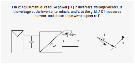
All commercially available grid-tie inverters are able to supply lagging or leading current. This is achieved by monitoring the current output of current transformers and adjusting the voltage output of the inverter to provide the required phase difference.
A power factor of ±0.9 requires a phase difference of ±25.8°, (see fig 2). As is evident, there has to be a small impedance across which the phase difference between the inverter voltage and the grid voltage is developed. The technology was in earlier days available on three-phase inverters. Single phase inverters can be made to do the same tricks by phase shifting the grid voltage as measured on line, by 90° and using the latter as the reference for creating the phase difference between the inverter voltage and the grid voltage.
More on voltage support: the ability of varying the current phase angle with respect to grid voltage increases the scope for voltage support. Many inverters are able to support volt-var and volt-watt operation.
The two modes function sequentially, initially in volt-var mode whereby as grid voltage increases, inverters supply lagging current (vars) and if unable to bring voltage downward sufficiently, the volt-watt mode reduces in-phase current (i.e.: real power) to further reduce voltage.
Grid-forming inverters and synchronicity
Grid-forming inverters are voltage-sourced, voltage-controlled inverters, suitable for microgrids and also for inclusion in large grids, although the latter requires acceptance for connection by network providers. When connected to a source of energy such as a battery, they are similar in many ways to a synchronous generator. They can have identical types of control such as droop control (frequency-power; voltage-vars) with ‘synthetic’ inertia, through various forms of feed-back control.
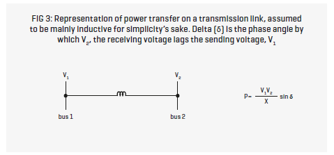
Grid-tie inverters rely on the grid for synchronisation as already explained, and because of this require steady conditions; not only reasonable constant voltage but also constant voltage angle. The latter is not self-evident so a brief explanation is in order. In electrical power transmission on the high voltage grid with a generator at one end, and a substation at the other end, there is a voltage phase angle difference between the two ends (see fig 3).
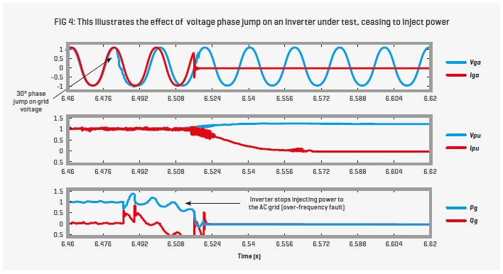
When the amount of power transmitted changes, so does the phase difference. Sometimes there is an abrupt change due to a change in load, a fault, a sudden change in power required by the substation, etc, and that causes the phase difference (voltage angle) to ‘jump’ to a new value.
When this happens, the inverters in the distribution grid have to resynchronise—remember, the phase locked loop voltage phase angles between the inverter’s internal oscillator and grid have to be in step (see fig 4). The time to resynchronise will vary between inverters, causing them to exchange power between themselves, resulting in voltage oscillation. The same voltage oscillation can occur after faults in the network, when previously disconnected inverters are reconnected as reclosers operate.
Maximising power
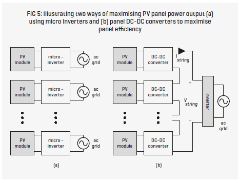
The maximum power point tracker, a feature of all solar inverters is being replaced by two main versions of newer inverters, micro inverters and inverters with distributed maximum power point trackers (MPPT). The former employs a multiplicity of inverters by allocating a lower rating power inverter to a small number of panels, and paralleling the AC outputs of the inverters.
Micro inverters are suitable for commercial installations where many panels are installed. Distributed MPPT employs individual MPPTs per panel or small groups of panels in panel strings. The technology has a big energy conversion efficiency advantage compared to single or dual MPPTs. Dual MPPTs have the advantage that they can maximise power when there are groups of panels in two different roof locations. The MPPTs are paralleled to the DC link of the inverter, and the groups of panels must have the same open circuit voltage.
Distributed MPPT provides maximum power for individual panels or small panel groups in a string, allowing for small variations in power production and overshadowing which reduces string current and output power. In fig 5, the use of module integrated converters (MIC) is shown in a simplified schematic. Note, that unlike the case with paralleled MPPT, the MICs are in series, conducting the string current.
A way of viewing the operation of the distributed power tracker is to see the function of the individual MICs as DC-DC voltage converters so that for the one string current maximum power is obtained. For maximum power harvesting, the MICs must be wired in parallel with all bypass diodes, so that per panel, typically there would be four or more MICs. Of course, there is no such thing as a free lunch, any more than that all those MICs do nothing else except boost energy harvesting, because DC to DC conversions also cost in energy loss.
In the case of micro inverters, the voltage available from one or two panels is too low, thus requiring significant DC to DC boosting by a typical factor of ten with attendant significant energy loss.
The future for solar inverters
The growth in installations of ‘behind the meter’ solar seems unstoppable. In many quarters, and certainly in ‘consumer land’ this burgeoning in ‘home grown’ electricity is seen as highly desirable. However, for distribution networks there are big problems, e.g. voltage rise but beyond the distributors, there is a looming grid stability issue. For example, in the case of South Australia, minimum power flow due to domestic, industrial and commercial solar during large parts of the day, puts the State’s electrical stability at risk if there are network faults which cause the solar community to drop out through anti-islanding protection in the inverters.
In the case described, there would be power rush on the interconnector to Victoria very likely resulting in the operation of under frequency protection relays and islanding of the State. As things stand there is no provision for guarding stability. Were inverters able to provide ride-through, then that could help in guarding against instability scenarios.
But there’s more; in our great enthusiasm for green power, there is the tacit assumption that somehow everything will work just as in days of yore. But frequency stability provided by very heavy, large rotational inertia generators is not replaceable other than in theory. Inverters can mimic inertia—but that’s the stuff of lots of academic papers—not actual experiment. Interesting times are ahead.
-
ADVERTISEMENT
-
ADVERTISEMENT

