Reducing the cost of underground cables: thermal resistivity
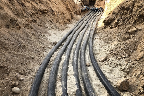
Underground cabling is a tricky topic with many variables impacting their performance, safety risk and compliance. GSES conducts an experiment on underground cables, the different types of thermal resistivity and looks at how it hits the hip pocket.
The performance of all electrical cables is affected by a large number of variables, like how closely together they are installed and the temperature of their surrounding environment. When these variables are not properly considered, there is a serious risk that the cables will be either oversized, resulting in unnecessary costs, or undersized, resulting in standards non-compliance or in the worst case, damage or injury to equipment or people.
ADVERTISEMENT
What has temperature got to do with it?
The fundamental problem being solved when sizing a cable based on current-carrying capacity (CCC) is ‘how much current can be pushed through this cable without it overheating?’. Standards like AS/NZS 3008.1.1 or IEC 60287 answer this by specifying the maximum current the cable can carry (for given environmental and installation conditions) without its temperature going above the rating of its insulation material.
When cables are installed underground, their ability to dissipate heat depends on the thermal resistivity of the surrounding soil. Generally speaking, a soil’s thermal resistivity is largely a function of its water content, although other characteristics like porosity will also have an impact. Much like bulk insulation in building construction, dry soil with high thermal resistivity will trap the heat at the cables, quickly driving the temperature up.
The thermal resistivity of the soil can be determined by lab tests of bore hole samples, which are generally taken from a site during a geotechnical survey. By making it easier for an underground cable to release heat energy into the surroundings, we can increase its CCC without increasing the size of the conductor.
The experiment
We can use thermal modelling and simulations according to IEC 60287 to demonstrate the benefits of a low-thermal resistivity environment for buried cables. Where the thermal resistivity of the soil at a site is higher than desired, it is possible to manage the negative effects by surrounding the cables with a lower thermal resistivity material.
Existing soil (no bedding sand)
In scenarios where the thermal resistivity at a site is relatively low, the cheapest and easiest option is to rely mainly on excavated material (i.e. when digging the trench) as backfill. In these cases, the thermal resistivity of the existing soil will impact directly on the CCC of the buried cables. In the experiment below, we will consider the following circuit:
- 400V (ph-ph) AC
- 4x1C (3ph+N) 300mm² Cu X-90 cables per conduit
(X-90 cables are rated for a maximum conductor temperature of 90°C) - 4x 100mm conduits buried with 500mm coverage, 50mm clearance between conduits
- Daily Loss Factor = 0.4
(The Daily Loss Factor, as defined in IEC 60853, is a way of describing how much of the time the current flowing in the cable is less than its peak value, and is particularly relevant for solar PV DC and AC circuits. Check out our previous article below for a more detailed explanation of how this can be used to get the most out of your cables: “Specialised Cable Sizing of Complex Electrical Circuits”)
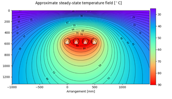
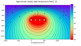
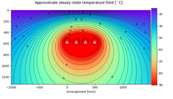
The combined CCC and approximate thermal diagram for each case is presented below:
As the thermal resistivity increases, the CCC for this circuit decreases drastically, and it can be seen that the temperature rise in the soil is concentrated around the cables. For this reason, it is essential that the soil conditions are accurately measured and included in derating or modelled simulations when designing an underground circuit.
Using thermal sand to decrease the thermal resistivity of the cable’s environment
In cases where the existing soil is found to have high thermal resistivity, a common response is to simply keep increasing the size and number of cables in the ground until the CCC is high enough for the purpose. Not only can this approach be costly, but it also only possible where there are no constraints on the number of cable terminations and/or trench width/depth.
Rather than just increasing the amount of conductor material, it can be cheaper to use a thermal bedding sand (with low thermal resistivity) to improve heat transfer away from the cables to increase their CCC. Encasing the conduits in thermal sand allows heat to be more effectively conducted away from the cables, allowing them to run at a higher current without exceeding their maximum allowable temperature. In the example below, a commercially available thermal sand with thermal resistivity of 0.85mK/W is installed around the conduits, and the CCC re-calculated. AS/NZS 3008.1.1 recommends that the thermal sand layer have a minimum thickness of 200mm ($28 per metre of trench), although a 50mm thermal sand layer option ($9 per metre of trench) is presented for comparison.
| Total CCC (IEC 60287) | |||||
| Case | No Bedding Sand | 50mm layer 0.85mK/W Bedding Sand | % Increase | 200mm layer 0.85mK/W Bedding Sand | % Increase |
| 1.4 – TR = 1.2mK/W | 1649.3 A | 1687.1 A | 2% | 1737.8 A | 5% |
|
Figure 1.4 – 50mm and 100mm bedding sand in soil with a thermal resistivity of 1.2mK/W |
|||||
| 1.5 – TR = 2.156mK/W | 1346.6 A | 1428.4 A | 6% | 1553.6 A | 15% |
|
Figure 1.5 – 50mm and 100mm bedding sand in soil with a thermal resistivity of 2.516mK/W |
|||||
| 1.6 – TR = 3.85mK/W | 1066.6 A | 1164.3 A | 9% | 1333.4 A | 25% |
|
Figure 1.6 – 50mm and 100mm bedding sand in soil with a thermal resistivity of 3.85mK/W |
|||||
The results show that the use of thermal sand as bedding and backfill surrounding the conduits can substantially increase the CCC of the circuit, by allowing the heat generated in the cables to be “dumped” into the surrounding soil. The effects are greater when the thermal resistivity of the original soil is high, and when the thickness of the layer of thermal sand installed around the conduits increases.
Cost comparison
Let’s pretend now that the circuit was initially designed to be rated to 1600A with 4x circuits in parallel, based on an assumed thermal resistivity of 1.2mK/W. The geotechnical survey has now been completed, it has been found that underneath a thin layer of topsoil, the underlying substrate is extremely dry clay with a thermal resistivity of 3.85mK/W. To return the CCC to its original level, the following options are considered:
| Description | Approximate Extra Cost (including bedding sand, cables and conduit) |
|
| A | Install no thermal bedding sand, just add more parallel circuits: 3x additional parallel circuits are required | $610/m |
| B | Install a 50mm layer of thermal bedding sand, add more parallel circuits: 2x additional parallel circuits are required | $415/m |
| C | Install a 200mm layer of thermal bedding sand and then add more parallel circuits: 1x additional parallel circuit is required | $230/m |
Considering only the material costs, Option C with the 200mm layer of bedding sand is the most cost effective. Additional considerations for this option include the freight and storage of the thermal sand and the plant equipment required to move and install it.
Conclusion
Safety should be the number one priority when designing and installing an electrical system, with efficiency and reliability following close behind. When it comes to underground cables, the impacts thermal resistivity of the surrounding soil must be verified and considered in their design to ensure safe operation, but the same phenomenon also presents an opportunity for creative and cost-effective solutions to be implemented.
GSES offers detailed cable sizing and derating analysis tailored specifically to our clients’ needs and those of their site. If you would like to find out more about the services GSES can offer please contact our design team on
-
ADVERTISEMENT
-
ADVERTISEMENT


