Charging ahead with electric cars
 Australia’s take-up of electric cars is slower than elsewhere, but despite a few issues this way of travel is sure to gain traction. Phil Kreveld reports.
Electric motor cars in their modern form have been around for more than 20 years, mainly as hybrids.
In the past five years or so, all-electric vehicles (EVs) have come onto the Australian market but sales are low (1,126 sold in 2017), and the total fleet is about 4,000.
Australia’s take-up of EVs is up to a decade behind other advanced markets, according to Andrew Fulbrook of HIS Markit marketing consultants in the United Kingdom.
ADVERTISEMENT
In Norway, 30% of new cars are EVs – due to government financial support and cheap electricity. About 80% of the nation’s power comes from hydro schemes.
There is no government support in Australia, or cheap electricity.
Yet emissions by the Australian transport sector are projected to be a worrying 100 million tonnes of CO2 equivalent by 2030. Replacing petrol and diesel vehicles with EVs would contribute substantially to a reduction in CO2 emissions.
To meet our CO2 reduction target by 2030 under the Paris agreement, a 55% reduction in transport emissions from current levels is required (if no further upward adjustments in renewable energy generation targets are made).
As things stand
EVs and plug-in hybrids (PHEVs) are expected to constitute a growing market. Consequently, new buildings in business districts are being equipped with networks of charger stations.
The main technical issues related to such vehicles are:
- the various charger plug and charger methods; and
- the different electrical systems employed.
Some of them use fast charging by external direct current (DC), others use alternating current (AC).
Another important consideration for the future is the power demand on distribution networks.
Fast charging an 85kW-h battery in four hours implies an average power draw (and higher initial peak) of 21.25kW. Multiply this by the number of vehicles charging at one time and the effect on distribution systems becomes evident.
Vehicle drive-trains
Hybrid drive-trains are generally more complicated than those of EVs.
 Figure 1 shows the basic drive train systems schematically.
Hybrid drive-trains vary in the sharing of motive power between an internal combustion engine (ICE) and an electric motor. EVs differ in the number of motors employed.
Hybrids use the electric motor to accelerate from standstill, and the ICE charges the battery once the vehicle is under way.
Motors, gearing and transmission
Synchronous and induction motors are used, offering a great advantage over ICEs because of high starting torque.
Synchronous motors have rotors with permanent magnet excitation (PMSM), as this is less bulky and avoids the use of slip-rings, which can cause mechanical problems.
Induction motors have squirrel cage rotors. Motors are powered by pulse width modulated (PWM) inverters thus providing speed control. Torque is controlled by inverter voltage regulation.
EVs don’t have a gearbox, as they are not plagued by the torque and engine speed characteristics of an ICE.
Motors have a fixed gear ratio torque conversion stage driving a differential to provide power to the driving wheels.
Open and limited-slip differentials are used. Some vehicles, such as the Tesla S, have an open differential with an ‘electronic watchdog’ that detects wheelspin and compensates by braking the wheel.
EVs with individual wheel motors don’t even need a differential.
Drives and dynamic braking
Three-phase inverters drive the motors, as shown by the basic circuit in Figure 2.
 The switching elements are usually insulated gate bi-polar transistors (IGBT) bypassed by freewheel diodes assisting switch-off of the IGBT.
The freewheel diodes also allow batteries to be charged via the inverter DC link when the vehicle is coasting or braking dynamically.
For dynamic braking in an induction motor the stator frequency has to be at a value less than the equivalent frequency of the rotor. This is readily achieved by the inverter.
Dynamic braking for PMSM involves field-oriented control. In outline, this requires sensing of the magnetic field vector provided by the stator with reference to the rotor. The vector leads the rotor during motoring and lags behind the rotor during generation (ie: dynamic braking).
During braking, therefore, the inverter switching is adjusted to provide the lagging angle of the stator excitation with respect to the rotor.
In hybrids, dynamic breaking is crucial because of limited battery capacity – about a quarter of that in EVs.
Lithium batteries
At the moment, lithium batteries are dominating the market.
Batteries are among the heavy components in an EV. The 85kW-h battery bank in a Tesla S weighs of 540kg.
In terms of energy density, petrol rates 45 megajoules per kilogram (MJ/kg) and the battery offers 0.567 MJ/kg (1MJ equals 0.277kW-h).
Lithium ion batteries have a very high energy density of about 200W-h per kilogram – as against lead-acid batteries at 40W-h per kilogram – and a high discharge to charge efficiency of 80-90%.
They will retain their storage capacity for 500 charge/discharge cycles based on 80% depth of discharge (DOD), although higher DODs severely limit their life.
Large-capacity batteries must have a reasonable range, as a typical EV uses 150W-h per kilometer. Rather than fully charging the batteries, some margin should be preserved for regenerative braking.
Battery management
The main aim in charging lithium batteries is to keep the temperature under control in order to minimise lithium plating of the anode.
In this regard much depends on the design. A thin, highly porous anode works best for very fast charging, as high as replenishing the full capacity in an hour. However, such a high charge rate is not used for electric vehicles.
A new battery technology, Enevate’s HD-Energy battery, is claimed to be inherently resistant to lithium plating during fast charging, and also during charging in low temperatures. It is not yet available in standard production vehicles.
High temperature increases the reaction rate with higher power output. However, it also increases heat dissipation and generates even higher temperatures.
Similarly, temperatures below 10°C impede the chemical process in cells. Unless heat is dissipated to keep the temperature below 60°C, thermal runaway can occur during charging.
There are generally two groups of liquids that transfer heat for thermal management:
- dielectric liquid, such as mineral oil, which can contact the battery cells directly; and
- conducting liquid (indirect-contact liquid), such as an ethylene glycol and water mixture, which can only contact the battery cells indirectly.
The front of a vehicle can capture air to cool the heat exchange liquid.
Cold-weather driving, as experienced in the Northern Hemisphere, is not much of a challenge in Australia.
Heat generated by the motor may be used for warming the battery. However, it might take several minutes before the battery is warm enough to provide full acceleration. Cold batteries charge more slowly, thus constraining regenerative braking.
Battery-supplied heating for passengers will limit the vehicle’s range. This is not a problem for hybrids, as engine heat engine is available.
When it comes to charge management, undercharged lithium batteries lose capacity permanently, necessitating special precautions on recharge circuits.
Lithium ion batteries cannot absorb overcharge. When they are fully charged, the charge current must be cut off.
A continuous trickle charge would cause metallic lithium plating and compromise safety. Over time, the open-circuit voltage will settle to between 3.7V and 3.9V per cell.
Charge management is a complicated technology because battery voltage must be maintained within tight limits.
In the Tesla S there are about 7000 batteries connected in paralleled strings. In order to keep cell voltages within limits, charge equalisation must take place.
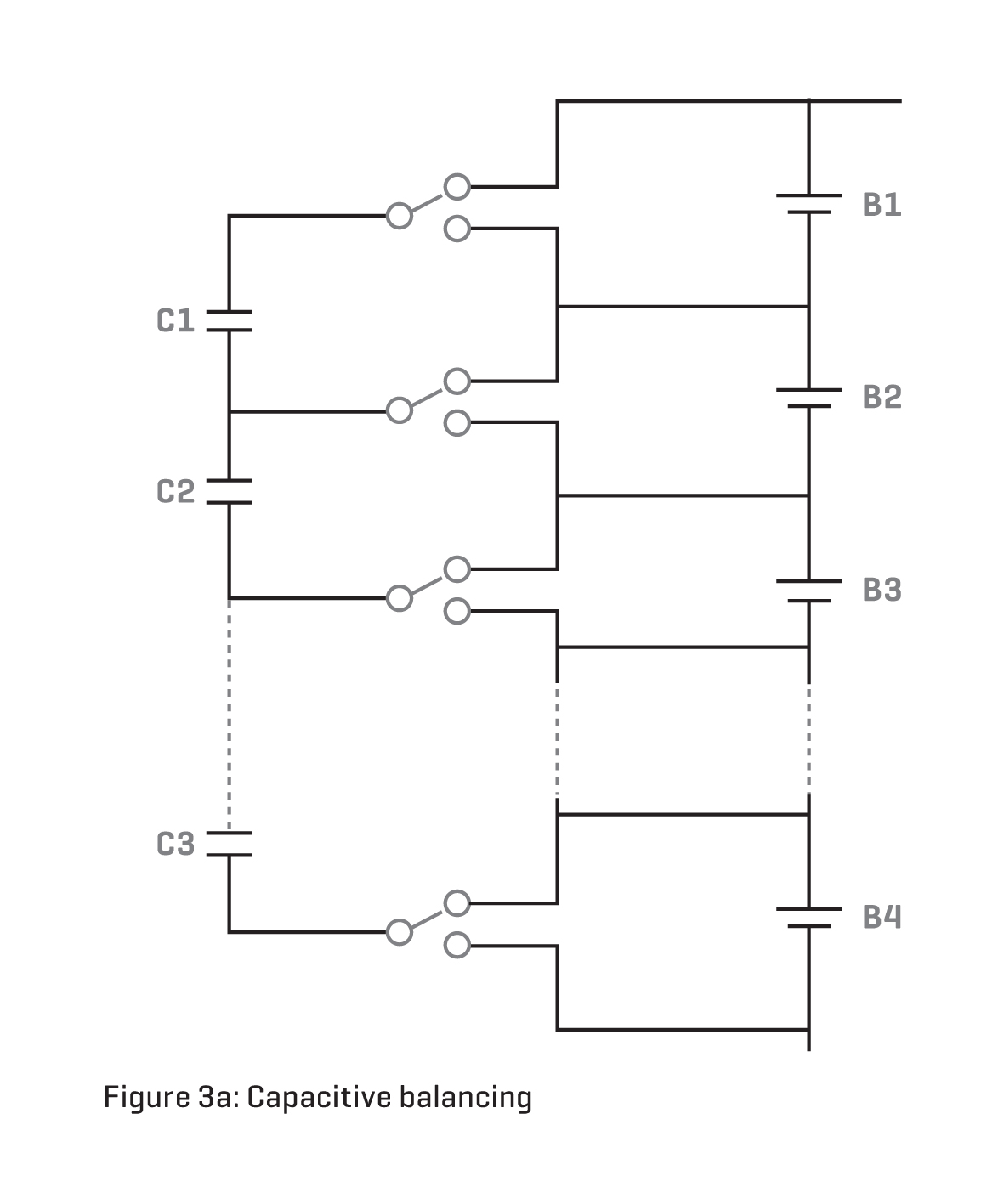
There are different ways of doing this:
- resistor strings across the cells (but this wastes battery energy); and
- capacitor and inductor charge transfer.
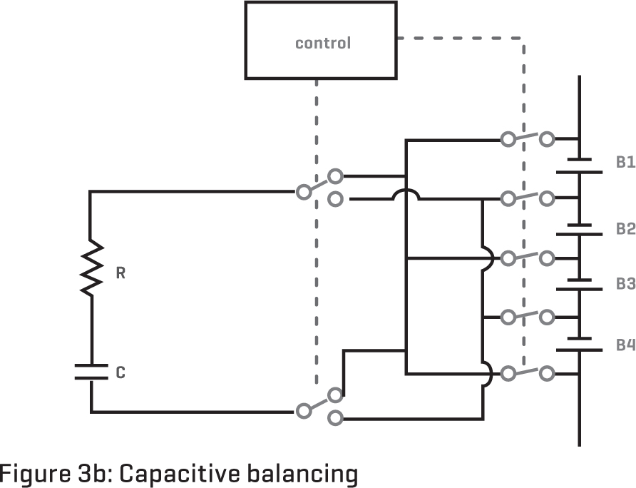
 The switched capacitor principle is illustrated in Figure 3a. The flying capacitor, which is far more economical, is shown in Figure 3b.
The scheme in Figure 3a requires n-1 capacitors and 2n switches for a string with n batteries.
 In Figure 3b only one capacitor is used, and n+5 switches (the switches are not mechanical; they are transistors).
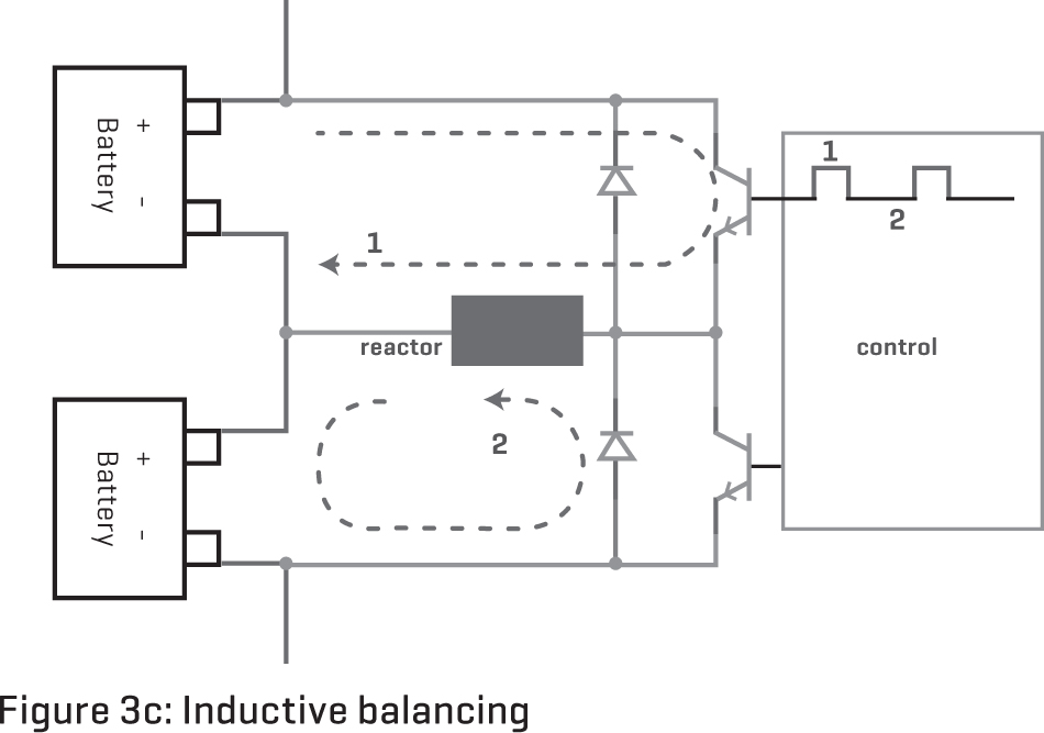
The method of switched reactors transfers energy from the cells with higher voltage to cells with lower voltage. This method works bi-directionally, usually comparing two neighbouring cells.
 Figure 3c shows one circuit of a switched reactor equalising two batteries. The transistor next to the block or cell with a higher charge is controlled with a PWM switch.
When switched on (phase 1), it draws current from this block through a reactor, which stores magnetic energy (1/2 Li2) where L is the inductance in henrys, and i the current in amps.
When switched off (phase 2), the neighbouring block is charged with this small amount of stored energy.
Figure 3c shows an inductive string controller controlled by a PWM switch.
Charging systems
There are two basic charging systems: AC output and DC output, the latter providing a fast charge.
EVs have their own internal charger circuit providing AC to DC conversion. The AC section for many EVs can be bypassed to allow direct DC charging.
Because of power restrictions for low AC voltage (220-240V), AC charging is slow and suited to overnight charging. DC charging requires a voltage in excess of the vehicle’s battery bank, typically more than 400V. At present there is no single Standard for fast chargers, making life complicated.
There are four widely used types of EV fast charger: SAE Combo, CHAdeMO, Tesla Supercharger and China GB/T.
Generally, an EV model is designed to accept one type only. In some cases, adapters can be used to take advantage of another type of fast charger. However, each has its own communication protocol, in addition to the physical design of the plug.
CHAdeMO is the trade name of a Japanese initiative for a fast charging method delivering up to 70kW of high-voltage (up to 500V DC) current via a special electrical connector. It has been proposed as a global industry Standard and is specified by the Japan Electric Vehicle Standard.
The connector includes two large pins for DC power, plus other pins to carry CAN Bus (controller area network) connections between the car and charging stations.
CHAdeMO was rapidly adopted in Japan, with about 5,500 stations deployed in 2017.
The SAE Combined Charging Solution (SAE Combo, or CCS) involves a J1772 plug with two additional DC fast-charging ports. The upper part is the J1772 plug used in the United States and the lower part has two DC power pins.
CCS supports slow and fast charging with a single port and uses power line communication (PLC), which is part of the smart grid protocols supported by regulations in Europe. CCS is used by Audi, BMW, Daimler, Ford, General Motors, Porsche and Volkswagen.
The Tesla DC Supercharging network provides the fastest broadly available charging: 120kW in an hour offering a range of up to 600km.
China GB/T was developed by ABB to be compatible with a Chinese fast-charging method. It uses a connector of same physical shape as widely used in Europe, with CAN control instead of PLC.
Fast chargers are expensive and therefore not suitable for private use. There are fast AC chargers but they require three-phase power, which the typical home doesn’t have.
Manufacturers of EVs generally limit the power of on-board chargers to keep the cost down. One idea is to use the vehicle’s traction electronics for charging batteries.
EVs and the grid
The charging current for EV battery chargers can pose harmonics problems.
 A bridge rectifier without any filtering draws an extremely peaky current (Figure 4), which is usually not a problem for low-power chargers.
However, for fast chargers it is dependant on the amperage fraction of the short-circuit capacity at the point of common coupling.
 The circuit in Figure 5 shows the principle of power factor correction (PFC). Note: the power factor is a combination of displacement and harmonic distortion (caused by the peaky current draw).
The switch T1 is either a metal-oxide semiconductor field-effect transistor or IGBT depending on power requirements. The active PFC circuit is basically a boost converter that is controlled to track the voltage.
This ideally results in a sinusoidal current and unity power factor. In other words, the active PFC circuit ideally makes the load look purely resistive.
 The schematic representation for a typical DC charger is shown in Figure 6. Noteworthy is the galvanic isolation provided by the transformer, which also raises the voltage for the DC charging section.
The full bridge inverter on the primary provides a voltage with a frequency of 2kHz or more.
Microprocessors and a communication link with the EV are required so that the correct charging profile for the battery is observed.
Vehicle batteries in principle can also feed energy back to the grid, and this is similar to solar photovoltaic battery storage.
Commercial schemes have been proposed, but we are some distance off in Australia.
EVs parked at designated ‘two-way energy flow’ kiosks could be charged when excess renewable non-dispatchable energy is available. When required, they could provide grid support.
Recycling batteries
Because of the relatively few EVs in use, recycling is not yet a major issue, although a market is developing if solar systems are taken onto account.
For lithium EV and PHEV batteries the focus is on collection and safe storage until enough are available to make recycling economically viable. When that point is reached, some components will be recycled locally and others will have to be sent to specialist recyclers overseas.
EVs – here to stay?
The short answer is ‘yes’, the world is embracing the concept.
The energy efficiency argument has two aspects: where does the energy come from and what does it cost?
An internal combustion engine typically has an efficiency of 20% (converting the fuel’s calorific value to mechanical energy). For petrol it is 45MJ per kilogram or 12.5kW-h per kilogram).
An electric motor has a typical efficiency above 80% (converting kW-h to mechanical energy).
The energy multiple in manufacturing a lithium battery – against the energy that can be extracted over its life time – is 30 or more. This is of the same order as petrol.
We can assume that the energy required in building the rest of an EV is about the same as for a conventional car.
It’s generally argued that transmission efficiency for an EV is better than for a vehicle with an engine because a gearbox is avoided.
So now it is a question of where the energy for battery charging comes from. If it is derived from a solar panel-inverter, the efficiency of acquiring the kW-h is about 15%. If the energy comes from a coal-fired power station, it is about 25%.
However, the marginal cost of a kW-h derived from sunshine is zero.
To wrap up: smaller batteries (lighter vehicles), more fast-charging stations, more green energy, and lower CO2 and NOx emissions must be the conceivable future.
-
ADVERTISEMENT
-
ADVERTISEMENT

