The panel game
 Medium-voltage and low-voltage grids will have to be redesigned, with remote access to inverters being a step towards smart networks. Phil Kreveld explains.
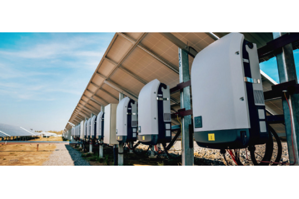
A few million solar panels have been installed on Australian roofs.
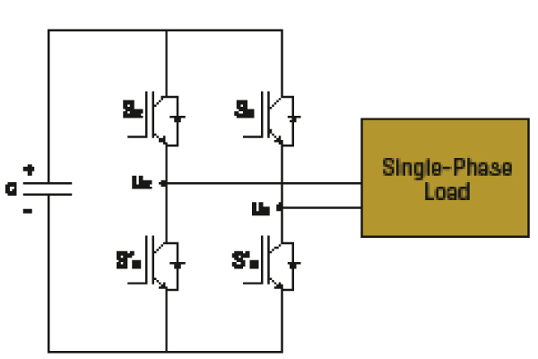
Most are grid-tie, single-phase, H-bridge inverters (Figure 1a) technically described as voltage sourced.
They are dispersed on the basis of individual solar system purchase decisions rather than for balance among the phases of three-phase low-voltage networks.
ADVERTISEMENT
They save money for residents and cause headaches for the networks. These headaches are summarised as:
- phase unbalance;
- voltage regulation;
- protection relay problems at substations; and
- harmonics
Networks are living with these problems and there is no solution in sight.
However, as inverters increase in output, the networks are imposing tough grid codes basically limiting the power allowed for feed-in.
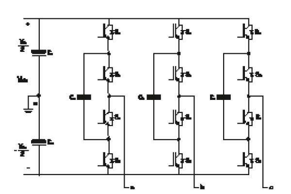
For ratings of 30kW and over, three-phase inverters are usually required (Figure 1b). The common version is the single-stage inverter (basically the H-bridge with an extra ‘leg’). The two-stage inverter (Figure 2) is suitable for high DC input, typically more than 600V.
Doubling the switching transistors makes for a more expensive product, and two-stage inverters are used in commercial and industrial installations. Three-phase inverters are more likely to provide phase balance, and that is of some advantage.
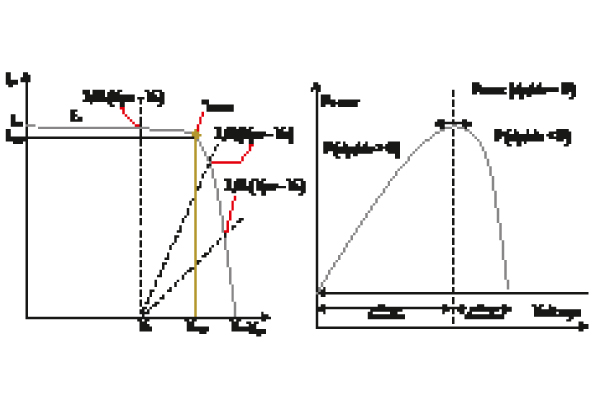
Figure 3a: The typical voltage current curve for a solar panel is shown on the left, and the power as a function of voltage on the right. The hill-climb procedure basically provides for small voltage steps starting at the lower voltage end of the power-voltage curve, until a further increment reduces power slightly.
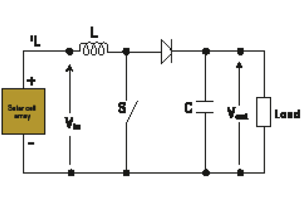
Maximum power point trackers (MPPT) are part of solar inverters with ‘hill climb’ or similar protocols for extracting maximum solar power from solar photovoltaic (PV) panels.
Figure 3a illustrates the concept of maximum power point, and 3b a basic maximum power point circuit (the DC link is connected to the inverter. Note that MPPTs are not used, or disabled, for inverters required to provide lagging or leading reactive power.
Alternating current (AC) power output can be maximised by using a sine wave modulated by a third harmonic, yielding a more flat-topped pulse width modulated (PWM) output with a higher root mean-square (RMS) AC power output.
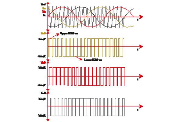
Figure 4: Basic operation of pulse width modulation (PWM). Note the triangular carrier signal, which provides the switching frequency as well as pulse width when intersected by the sine wave.
Figure 4 illustrates a typical, bi-polar PWM switching waveform for a three-phase inverter. Our focus in this article is on three-phase inverters.
Basic inverter types
Four types are discussed, and they are illustrated in Figure 5.
They are basically voltage-sourced, controlled-current inverters, except for the grid tie ‘prosumer’ (producer-consumer) inverter.
It operates at unity power factor in terms of power export, but it can ‘sink/source’ quadrature lagging load current (leading load current is also possible but rarely occurs in practice) by virtue of the free-wheel diodes mounted across the switching transistors (Figure 1b).
The free-wheel diodes, in addition to allowing safe switch-off of transistors, also can conduct reactive power flow into the DC link of an inverter.
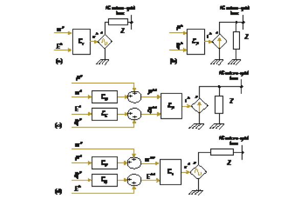
Figure 5: Various forms of grid-forming and grid-supporting inverters. Note that 5c is an example of current support (active and reactive current), and 5d provides voltage support (active and reactive voltage)
The other three types are grid forming (5a), grid feeding (5b) and grid supporting (5c/d).
Grid-forming inverters are suitable for use in micro-grids because they establish network voltage and frequency.
Grid-feeding inverters require voltage and frequency to be established, but they supply power and reactive power to take the pressure off from synchronous generators, for example.
The grid-supporting inverter can also help stabilise voltage and frequency. Grid-forming inverters are connected via low output impedance to the grid.
As mentioned in this issue’s article on micro-grids, a voltage-forming inverter, probably fed by a battery energy management system would be needed to set voltage and frequency for the grid. Grid support, on the other hand, has become a reality.
Grid support
As mentioned, grid support is becoming an essential task of solar PV inverters.
Essentially this requires three-phase inverters with the capability to supply quadrature power as well as usable power.
Single-phase inverters can supply quadrature power, but they are not commercially available. In any event – given the random nature of phase distribution for domestic solar PV – they would be of no practical use for quadrature power by adding to the imbalance of three-phase circuits.
Although loads (air-conditioners, refrigerators, pool pumps) rarely have leading power factor, the ability to provide leading quadrature power is important for voltage support.
Furthermore, lagging power for voltage regulation downwards may be necessary at times. With high levels of feed-in from solar PV causing net reverse power flow (towards the substation), voltage can rise beyond the upper limit.
At present, that eventuality is taken care of by shutting down the inverter, generally at 264V, single phase. This is hardly a satisfactory solution given that ‘behind the meter’ energy generation is growing in importance for future electrical energy generation planning.
High-voltage (HV) transmission, medium-voltage (MV) and low-voltage (LV) networks have different impedance characteristics, going from mainly inductive for HV to mainly resistive for LV.
Voltage support by means of quadrature power in HV is supplied by synchronous condensers (over-excited synchronous motors, on no load).
In MV distribution, capacitor banks provide leading power factor – or a combination of thyristor-switched inductor/capacitors (STATCOM) provides leading and lagging power factor.
In LV distribution there is often no control provided, save for no-load tap changing transformers. Voltage control is mostly at substations and is provided by on-load tap changing transformers.
In Figure 6, a section of an LV distribution line is shown. Generally, LV distribution is by radial ‘topology’, radiating out from the substation, essentially without ‘meshing’ – the latter providing some additional security against partial network failure.
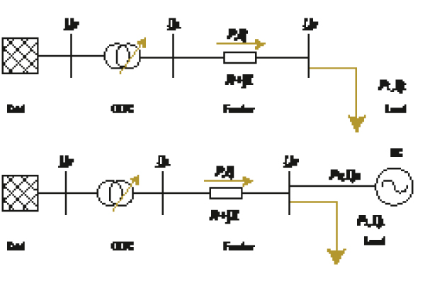
Figure 6: A schematic representation of a feeder in a distribution network with and without distributed generation.
The voltage difference between points 1 and 2 is given by the formula below (applicable to mainly resistive power lines).
R is the resistance of the line. X (although lesser in ohms than R) is the generally inductive impedance. PL and QL are respectively the power and quadrature power drawn by the load. When distributed generation is part of the network, voltage drop can be counteracted by local distributed generation, eg: a solar PV system, as shown by the relationship below.
The above formula shows clearly that as generated power PG increases, the voltage drop DV decreases.
The reactive power available has an effect as well. If the solar PV inverter can be made to supply reactive power QG, then DV can be made to reduce by means of leading reactive power (-QG) or to increase by providing lagging reactive power (+QG).
More than feeding in
The importance of providing lagging and leading current as well real power (in-phase current) has been established.
Three-phase inverters sold in Australia must be able to supply lagging and leading reactive power. Notwithstanding this requirement, the network control systems for managing inverters remotely has not been established.
Reactive control, whether lagging or leading, basically limits usable power as illustrated in Figure 7.
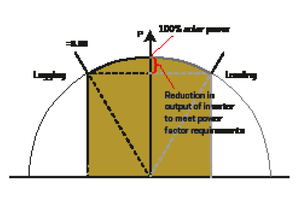
Figure 7: Solar panel DC power is indicated by the circle quadrant, and providing reactive power decreases the useful power available.
The circuitry required is obviously more complex than is the case for unity power factor inverters. The block diagram for a grid-supporting inverter is shown in Figure 8.
Rather than explaining the complete system, the essential control features are mentioned here.
The reference to ‘abc’ in various parts of the block diagram indicates three-phase voltage or current parameters (ie: the a-phase, the b-phase at 120°, and the c-phase at 240°). A set of three-phase parameters (‘phasors’) rotates at line frequency of 50Hz.
The essence of power factor control is to ‘retard’ or ‘advance’ the current waveform in each phase with respect to the voltage. To make this possible, the current and voltage ‘abc’ phasors are converted to d-q parameters (also called space vectors); ‘d’ representing the ‘real part’ and ‘q’ the ‘quadrature’ part.
The grid voltage is measured at the point of common coupling, and the voltage phasors are converted from three parameters to two, ‘d’ and ‘q’.
Current output of the inverter is measured by a current transformer (next to the inductor connected to the inverter output). The control circuitry can control the angle between the two (current, and voltage) d-q space vectors thus providing real as well as quadrature, or reactive power.
When the sun doesn’t shine
In essence, the circuit of a three-phase inverter is no different from an active harmonic filter.
Apart from harmonic correction, active filters are also used for power factor correction.
However, the circuit of three-phase power switches can also be used for supplying reactive current to a network.
As the circle diagram in Figure 7 shows, in theory, no power is required to provide reactive current. In practice, the switching losses of the three stacks of switching transistors must come from somewhere.
The capacitor, which is part of the DC link, furnishes this energy and the grid, by way of the free-wheel diodes (the diodes mounted across the switching transistors), replenishes the energy lost by the capacitor during reactive current injection.
The future
Given the doubt surrounding electrical energy policy, forecasting is a difficult.
However, there is some certainty that MV and LV distribution grids will require a redesign. Voltage variation is a problem that is likely to become more of a ‘feature’ in distribution networks.
Deployment of more on-load tap changing transformers is likely, but remote control of inverters is on the cards to limit the extra capital expenditure.
At the moment, grid codes restrict the ratings of inverters, but eventually these restrictions will have to be renegotiated in return for remote access. This will be an early step towards smart networks.
-
ADVERTISEMENT
-
ADVERTISEMENT

