Shine a light on solar
The basic principles of photovoltaic systems make useful reading for non-specialist electricians installing all or part of a system. Phil Kreveld sets them out.
 Lots of companies sell items that make up a solar system, but their mission in life is not necessarily doing the installation. That falls upon the humble electrician.
These companies don’t necessarily have accreditation with the Clean Energy Regulator (CEC). However, they can employ contractors, who must be accredited.
ADVERTISEMENT
The company supplying the equipment will carry the warranty obligation, but the electrician installing the system has to sign off, and green energy rebates are awarded on that basis.
Electrical Connection is providing the necessary information and website links to bring non-specialists up to speed and closer to accreditation.
The focus is on rooftop, grid-connected PV systems, but because storage batteries are becoming more economical – lithium-ion types in particular – increasing adoption is likely as feed-in tariffs fall or disappear.
PV panels
The technology behind PV panels is well developed and there are more than 50 major suppliers worldwide, most of them in China.
In Australia the main panel types for rooftops are polycrystalline and crystalline silicon. Each has its advantages, but these are not major performance differentiators.
The customer for a grid-connected system is interested only in saving as many kilowatt/hours as possible. In practice there are enough variables having little or nothing to do with PV panel performance that influence the result – the AC kilowatts and kilowatt/hours.
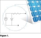
Figure 1 shows a typical rooftop panel with 60 photovoltaic cells connected in series. The inset shows an equivalent circuit diagram of a single cell. It is a current generator with a diode across it, plus a bit of lead resistance.
 The higher the intensity of sunlight (W/m2 – tech name: insolation), the more current is generated. The complete panel will crank out about 300W under maximum conditions (standard temperature condition – STC), or something close to that, with a voltage of about 30V. The current is therefore 10A and the voltage per cell about 0.5V.
The circuit diagram for the complete panel can be visualised as a 10A current generator with a single diode (made up of 60 in series, a ‘lumped’ diode) across the current generator.
How important is voltage?
A single-phase, grid-connected PV system has to supply 240V AC (that’s rms voltage), and the peak voltage is therefore 142% of that, or 341V.
The DC link voltage supplying the inverter can’t be any lower than the peak AC voltage (unless the inverter connects to the grid via a step-up transformer).
The smallest commercial PV system is 1.5kW (six panels), which at 300W each yields 1.8kW. However, with all six connected in series, the voltage output is 180V DC. It’s not a problem, because inverters can cater for lower DC output using a boost circuit. More of this in the inverter section.
Series or parallel
PV panels can be connected in series or parallel, and either way it’s the total number that determines the aggregate power.
For battery charging, the connection is in parallel, ie: current UP and voltage DOWN. Otherwise there would have to be a buck circuit to bring voltage down closer to the battery voltage.
Maximum power tracking
In inverter specifications there’s always reference to maximum power point tracking (MPPT).
The idea is to have the right combination of voltage and current for the highest DC watts output.
If the PV array is open circuited, you’ll get maximum voltage, zero current and zero power. If short-circuited, there will be zero voltage and maximum current, and again zero power output.
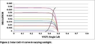
Somewhere in between is the maximum power point. Figure 2 shows a set of current-voltage curves at increasing insolation for a typical panel. The power curves are in a different colour and, as can be seen, maximum power is close to the open circuit voltage but moves to lower voltages as insolation decreases.
 MPPT control is often complicated, but a simpler version is based on a proportion of the open circuit voltage. In a later article on inverters there will be more on MPPT. For the moment it suffices to know that MPPT is a really crucial part of a solar inverter.
A gable roof (say, with a north-south roof ridge), can have panels on both sides to make use of morning and afternoon sun. The inverter can have two MPPTs to maximise the individual array power outputs. For maximum power the panels should have identical characteristics.
Shading and orientation
Figures 3a and 3b show two panels in series, or it could be a larger number (a ‘lumped’ equivalent circuit is shown similar to Figure 1).
 Shading is a problem, and if a cell in a PV panel is shaded then the series link is broken and no current can flow. In Figure 3a that’s the situation – no current, whereas in Figure 3b a bypass diode is fitted across the two terminals of the shaded panel. Power and voltage are down, but the overall system is still working.
For panels in parallel, blocking diodes (Figure 3c) are used to prevent a panel or assembly becoming a load rather than a source of power, eg: through a short circuit.
PV panel installation guides make the point that panels of varying characteristics should not be ‘mixed’. In practice the advice is to stick to one manufacturer and type to avoid problems associated with reliability and power performance.
Installing panels so that they receive maximum sun is the responsibility of the system contractor. The website of the Australian PV Institute is useful for planning. It allows selection of individual houses, etc, on maps and the visualisation of any shadows.
Common sense tells us that the sun shining normally on a panel will give the maximum insolation, whereas glancing sunbeams will yield very little.
In practice, overcast skies make easy geometrical arguments less relevant. Furthermore, the lower the sun’s position the more air there is in the path to absorb some of the energy.
Inverters
There’s a huge number of inverters on the market, but for most domestic PV systems the single-phase, transformer-less type is used.
As a rule, very little technical material is made available by suppliers. When things go pear shaped, board replacement is the only way to get back to a functioning unit.
Transformer-less inverters are much lighter than those with a 50Hz transformer grid connection. Technically both do the same job, but the output transformers reduce efficiency by several percentage points. It may not sound much, but it makes a big difference to the energy delivered over the life of the PV system.
Both types of inverter systems require a safety ground connection for the PV panel array. Transformer-isolated systems can also have a functional system earth on the PV panel side – not so transformer-less systems.
There are inverters that connect directly to the grid like transformer-less systems, but they have an intermediate high-frequency transformer between the PV panel array and the DC link of the inverter. In this type of inverter the PV array can have a functional system earth.
The MPPT feature of inverters is important. The role of the MPPT is to adjust the PV array voltage for maximum power and to provide a sufficiently high voltage to the DC link feeding the inverter. (As mentioned, a single-phase system needs a DC link voltage exceeding 341V.)
For a PV array on one side of the roof only, the panels are wired in series and have to deliver sufficient voltage to the inverter’s DC link.
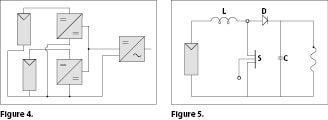
For PV arrays on two sides of a roof, each has its own MPPT, which has its output in parallel with the other MPPT to supply the inverter DC link (Figure 4).
 Other than the simple means of MPPT control by reference to open circuit panel voltage, all other methods use intricate software, and technical details are not supplied as a rule.
MPPT circuits can be visualised as in Figure 5, which illustrates a typical boost circuit. The switch (S) is a transistor, turned on and off at a varying duty cycle determined by software. That duty cycle is the ‘guts’ of the power tracking.
With the switch closed, current builds up through the inductor (L). When it opens, the inductor current flows through diode (D) to add charge to capacitor (C). The DC link draws current from the capacitor, reducing the voltage across it.
Most grid inverters deliver unity power factor output. The house load may well have some motors requiring lagging power factor. Irrespective of feed-in, the grid has to supply the lagging reactive current to these loads.
The reason for unity power factor is that the grid synchronises the inverter, allowing current from the inverter to flow between voltage cross over points only. For an off-grid inverter (basically the same in circuit design) something different happens.
All inverters have freewheel diodes connected across the transistors making up the inverter bridge and these can conduct current back into the DC link – reactive current, exactly the same as happens in a variable frequency drive inverter powering an induction motor.
A vexing aspect of grid-connected inverters is ‘over production’ of electric power. The more the sun shines the more energy is put into the DC link via the MPPT and the inverter can deliver more current to the grid.
Depending on the impedance of the supply line, the voltage can rise and, because inverters have top as well as bottom voltage limits, the inverter will disconnect from the grid when these limits are exceeded.
This is a real problem where the inverter is part of a street scene in which every house has a solar PV system. The under-voltage limit is a safety measure (anti-islanding) to allow disconnection should a power failure or brown-out occur. In that case linesmen don’t want to encounter voltage unexpectedly.
Although still not commonly available, grid-connected systems with battery storage in years to come will be able to store excess production and use it at night. Control software, sometimes called ‘peak shaving’, already exists for commercial three-phase PV systems.
Grid-connected household systems are also being installed, although due to price there are few installations, and more space is required (one car space less in the garage).
Figure 6 shows a block diagram. In this system the PV panels charge the battery bank and supply the DC link of the inverter. Excess energy is fed to the grid, but at night the battery bank supplies household needs.
 The time may come when households will be connected by a 10A rather than a 60A service line, because battery storage will make consumers far less reliant on the supply grid.
Switchgear and safety
A solar PV system must have DC isolation switches as well as AC switchgear.
DC is much more difficult to interrupt than AC, which has zero crossover points every 10 milliseconds. The moment a DC circuit is interrupted, ie: the PV array, its self-inductance will want to keep the current flowing, because energy is stored in its surrounding magnetic field.
As a switch begins to open, an arc is drawn and continues to lengthen as the switch opens more, maintaining a low voltage across the arc. Overheating and melting of switch components can and does occur.
The idea is to rapidly allow a high voltage to be developed across the switch. In the first place, switches designed for AC are physically far too small to do the job. DC switches are often made up of two or more switch sections opening at once.
DC circuit breakers often use a magnet to blow the arc into a long path in order to interrupt the current flow. They are ‘polarised’, because you have to strictly observe the direction of current flow. Otherwise, instead of the arc being blown out, it is drawn in and not extinguished.
Polarised switching equipment is not allowed in Australian installations.
Earth leakage
In common with other electrical installations, earth leakage protection is required.
The transformer-less inverter system has floating PV arrays. Although there is a safety earth, no galvanic leakage is possible other than through build-up of somewhat conductive dirt.
The PV panels have large areas that can therefore have large capacitance to ground (think of a steel roof), and voltage ripple on the DC link can cause earth leakage current to flow from panels to earth. For the single-phase installation, the ripple is 100Hz and is minimised by parallel connected capacitors in the DC link.
The installation of earth fault alarms for functionally earthed and floating arrays became mandatory in July 2013. This obviously raises issues regarding updating older systems.
-
ADVERTISEMENT
-
ADVERTISEMENT

