Pardon the interruption
Technical aspects of the uninterruptible power supply will be of interest to electrical contractors. Phil Kreveld provides an overview.
This article deals with the static uninterruptible power supply (UPS), the rotary storage type (RUPS) and the diesel rotary storage type (DRUPS).
The accent is on large systems – 500kW and higher. Almost invariably, these are used in tier IV redundant power supplies.
ADVERTISEMENT
Although redundancy is imperative for failsafe conditions, the many ways in which it is achieved are not discussed in any detail, because much depends on individual sites. The Uptime Institute – an independent advisory organisation focused on improving the performance, efficiency and reliability of critical infrastructure for the information economy – defines four levels:
- Tier IV: Fault intolerant site infrastructure.
- Tier III: Concurrently maintainable site infrastructure.
- Tier II: Redundant capacity components site infrastructure (redundant).
- Tier I: Basic site infrastructure (non-redundant).
- Tier IV Guaranteeing 99.995% availability.
Tier III Guaranteeing 99.982% availability.
Tier II Guaranteeing 99.741% availability.
Tier I Guaranteeing 99.671% availability.
Tier IV has all components fully fault tolerant, including uplinks, storage, servers, plus heating, ventilation and air-conditioning.
Although defined in IT terms, operating theatres, dialysis centres, etc, can be subject to the same requirements. Tier IV – in addition to duplication, triplication, etc, aspects to achieve redundancy – also implies special engineering measures, many of which are highlighted here.
UPS systems
- The systems dealt with include:
Battery-backed static inverters supported by diesel generators; - flywheel-backed (RUPS) static inverters (the energy stored in the flywheel takes the place of batteries, and the flywheel is driven by a motor generator) with long (more than 5-30 seconds) interruption support from a diesel generator; and
- DRUPS without batteries.
We can’t do justice to the ‘economy’ argument when choosing a particular system, as this depends on particular site requirements.
However, in the case of DRUPS, it is better that batteries are eliminated altogether. A battery is a limited-life storage medium, and in Tier IV there must be no risk regarding availability. Long power interruptions, outstripping battery capacity, must be taken into account.
Valve-regulated lead acid (VRLA) batteries are commonly used, although there are nickel-cadmium batteries in use for some major energy storage systems. VRLAs are considered to be reliable, with relatively low maintenance.
Notwithstanding the marketing arguments from suppliers, battery-backed UPS systems are usually employed for ratings below 500kVA. The energy storage density of flywheels is lower than that of VRLAs, and by a factor of 10 compared with Li-ion batteries.
Battery-backed static UPS
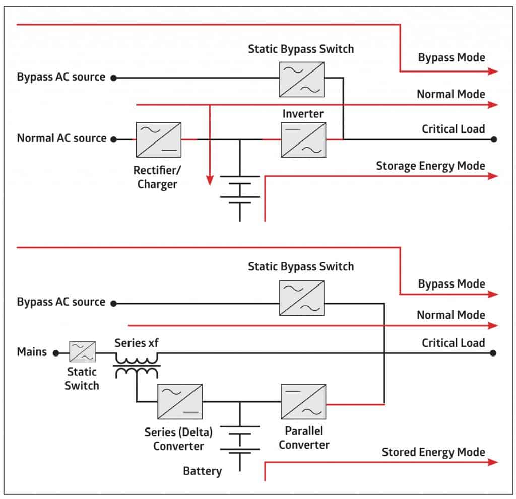
The two important topologies are the double conversion and delta schemes, as shown in Figure 1.
 Figure 1: The double conversion (left), and delta conversion schemes.
The double conversion topology has the advantage of isolating the load but is less efficient than the delta circuit.
The delta inverter provides incremental energy to the load (to make up for system losses). The primary of the delta transformer is, in effect, a variable impedance controlled by the delta inverter.
When the mains static switch operates to the off position, the load receives power from the parallel converter.
The series (or delta) converter makes up for any difference between the voltage on the output of the UPS and the voltage from the mains during normal operation. It also controls the input power factor to unity as it is it takes up mains current that is sinusoidal and in-phase with the mains voltage.
Furthermore the series-inverter controls the charging of the battery. The mains static switch protects against back-feed into the mains.
Double conversion systems can draw a considerably higher harmonic current than delta systems unless fitted with input filtering or harmonic traps. In both topologies the static bypass switch has to be synchronised with the inverter/parallel converter.
Flywheel-backed static inverters
The earliest forms of UPS systems seem to have been rotary, although that might be historically debatable.
A rectifier circuit maintained a battery bank driving a DC motor/AC generator. The inertia of the motor/generator provided change-over. A supplemental flywheel accommodated changeover in a few seconds, allowing a ride-through with sufficient frequency as well as voltage stabilisation.
The energy stored in a flywheel is proportional to the square of the rotational speed, and to its moment of inertia. In an ideal flywheel, all of the mass is concentrated at its outer radius, giving it a moment of inertia proportional to the square of the radius. Thus the energy stored is proportional to:
Where M is the mass, R the radius, and N the revolutions per second or minute.
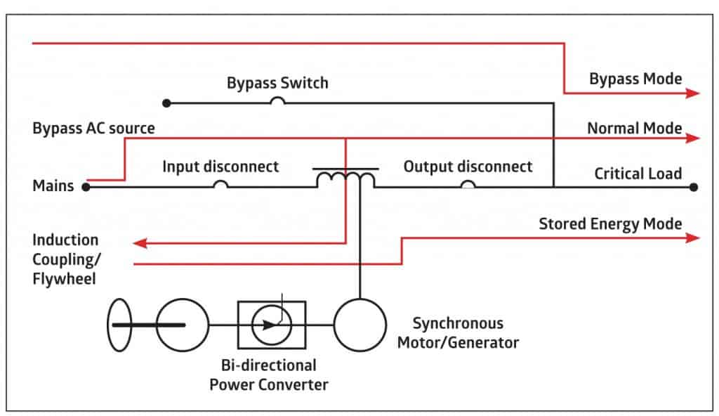
The principle of the UPS is shown in Figure 2.
 Figure 2: A flywheel-backed, double conversion UPS.
The AC motor/DC generator flywheel unit can be powered from the auto-transfer switch end or the inverter output.
The flywheel includes a hub that is formed from aerospace-grade steel, a high-speed permanent magnet motor generator, and contact-free magnetic bearings that levitate and sustain the rotor during operation.
Typically the DC generator will supply a 500V DC link. The manufacturer, Vycon, states that a 300kVA UPS would have up to seven seconds of uptime for the diesel generator to come on line. For additional capacity, flywheels can be paralleled.
DRUPS
These systems are generally devoid of battery static USP circuitry.
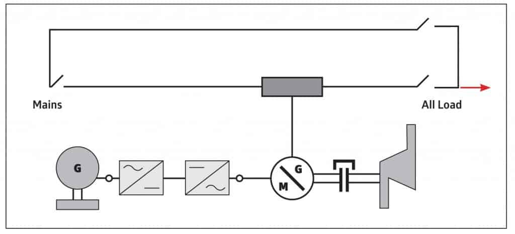
As in the system described above, the bridging energy during change over from mains to UPS is supplied by a flywheel. The flywheel inertia should be thought of as the combined inertia of a motor generator and coupling. The basic idea is shown in Figure 3.
 Figure 3: Basic topology of a DRUPS
The synchronous motor/generator is connected to the second motor/generator coupling flywheel combination via a bi-directional power converter.
Under normal mains conditions, the synchronous machine operates as an over-excited synchronous condenser, correcting power factor and drawing only energy for windage and bearing losses for the entire ‘rotating system’.
The buffer inductor (tapped inductor) has a low mutual inductance impedance but a high impedance providing isolation for the synchronous motor/generator, which regulates the critical load voltage.
A little more detail is shown in Figure 4, including the diesel generator necessary for longer mains failure periods.
 Figure 4: DRUPS, power converter, and diesel with coupling to synchronous motor generator
The power converter in Figure 4 looks a lot like the double conversion system discussed above. However, the DC link connecting the two motor generators has no batteries.
Rotary and static
When UPS systems go beyond 1MW, the DRUPS technology is more likely to be chosen.
Some practical considerations have been mentioned, namely that DRUPS as a system – without limited-life batteries – is a more ‘hardened’ system.
A clear advantage of battery storage is its efficiency compared with flywheel storage. The trickle charging during normal operation is about 10% of the energy required to maintain flywheel rotational speed.
In cost per kilowatt, high-power flywheels and lead acid batteries are of the same order. Lead acid batteries have a much higher energy storage density than flywheels.
On the other hand, if chosen for areas subject to poor power quality, batteries can be subject to excessive cycling and their service life will be reduced.
DRUPS systems (being AC without sine wave shaping) using pulse width modulation do not reflect harmonics into the mains.
Power factor
We are focusing on displacement power factor, whereas total power factor also takes account of harmonic distortion.
Displacement power factor is a substantial cost addition to many power bills. It is therefore of importance to UPS systems, since we are talking here of 1MW systems and greater.
In the case of DRUPS technology, the use of synchronous motors provides power factor adjustment, from lagging (running as a motor) to leading (running as a synchronous condenser), so that maintaining a power factor of unity is no problem.
DRUPS systems, being AC throughout, can be affected by the input capacitance of IT power supplies, thus exposing standby generators to leading power factor.
In static UPS systems, AC to DC converters can have much lower power factor.
Thyristor converters in normal full load operation have lagging power factors, the reason being that commutation to the off-state can only happen at zero current. Any inductive part of the DC link (usually an inductor-capacitor circuit) will extend the current on each half cycle.
If insulated gate bipolar transistors (IGBT) are employed in the AC to DC conversion, the displacement power factor is essentially unity because IGBTs can be gated on and off.
This is a more costly conversion, as freewheel (snubber) diodes must be used across the switching transistors (these conduct the current due to the collapsing magnetic field of inductors).
Lagging power factors are not problematic for standby generators unless lower than 0.7 when the automatic voltage regulator (AVR) runs out of excitation current control range.
Leading power factor is a problem, in that lower and lower excitation current is necessary to control voltage as more power is drawn. The AVR therefore runs out of range much more quickly and voltage can rise to dangerous levels.
Harmonics
The exporting of current harmonics is mainly a problem for static UPS systems.
In an unfiltered state the commonly used six-pulse converter generates more than 30% of total harmonic current distortion (THID). This can be reduced to about 7% by a second transformer and parallel connected six-pulse converter, making a 12-pulse converter.
The latter makes sense for higher rating UPS systems. For a six-pulse system the principal harmonics are the fifth and seventh; for a 12-pulse converter, the eleventh and thirteenth.
Passive filters for mitigating harmonics employ capacitors as parallel elements and inductors as series elements.
Under light IT load, the input to the UPS converter appears mainly capacitive, and that can be a problem for the standby generator. This is sometimes taken care of by switching out capacitors under light load conditions. The use of active harmonic filters removes the problem but adds substantially to the overall cost.
Operation with standby generators
Frequency stability is of importance – there are no golden rules, but it is an issue if the generator full load capacity is closely matched to the static UPS.
With a prolonged outage, say, in excess of 20 seconds, the generator will start up and supply the AC to DC converter. Frequency and voltage stability at the site should be such that the DC link battery bank is not being needlessly exercised.
The static UPS double conversion topology (Figure 1) is better suited to stable synchronisation than the delta conversion topology. This is because the former is entirely isolated from the mains (yet is mains synchronised under normal operation).
When a power outage occurs, the inverter supplying the critical load is self-synchronised, maintaining this state until power restoration when synchronisation is derived from the static transfer switch.
In the delta scheme, frequency stability is important. The inverter has to be in synch with the generator, because in essence it is regulating the voltage to the mission-critical load.
Frequency stability is the main issue for DRUPS systems. The employment of synchronous motor-generator-flywheel combinations provides a stable basis.
Diesel engines
Diesel generators, particularly when not fully loaded for extensive periods, are more prone to ‘wet stacking’.
Most standby generator systems up to 5MW use the reciprocating internal combustion engine as the power source to drive the generator.
Diesel is a convenient fuel source, and the compression ignition systems of diesel engines have a much higher thermal efficiency.
When a diesel engine is operated on light loads, it will not attain its correct operating temperature. When operated for extended periods, unburnt fuel is exhausted and noticed as wetness in the exhaust system, hence the term wet stacking.
The obvious solution is to run the generator set with an electrical load that reaches the designed operational temperature of the diesel, or approximately 75% of full load.
Prolonged operation at low load will eventually mean an expensive engine overhaul.
The use of resistor load banks to be switched in when light load conditions pertain is recommended. This can be an automatic switching-in, or as part of a regular maintenance procedure.
Battery and system monitoring
The monitoring of batteries is essential for UPS systems.
On-line monitoring requires string current monitoring, and also monitoring of individual cell voltages – that being necessary to prevent a cell of lower capacity being driven into reverse condition.
For preventive maintenance, an off-line ‘state of health’ test is recommended.
Capacity tests (discharge tests) should be done at the installation (acceptance test) within the first two years of service, and at intervals no greater than 25% of the expected service life.
For on-line battery monitoring, a radio-based method is preferable, as it obviates extensive cable harnesses. USB and RS-232 (serial port) connectivity may be suitable for small installations. However, data centre UPS systems should include internet protocol connectivity to allow remote management across an Ethernet local area network — the same mechanism that supports remote server, storage and other systems management in the data centre.
-
ADVERTISEMENT
-
ADVERTISEMENT

