On the grid
Solar panel arrays can be better distributed for maximum ‘collectible’ characteristics. Phil Kreveld discusses the principles.
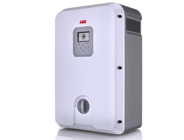 Solar photovoltaic inverters differ from other types, often battery driven, that are used for marine, outdoors and emergency supplies.
The main difference is that the DC input side, the DC link, has integrated maximum power point tracking (MPPT) circuitry.
ADVERTISEMENT
As discussed in the overview article, MPPT circuitry is necessary to extract maximum power from solar panels under conditions of varying insolation, overshadowing, panel surface temperature and the gradual changing of the sun’s elevation and azimuth angles during the day.
This article deals with grid-connected inverters. Although the single-phase versions are discussed in some detail, many of the circuit considerations apply equally to three-phase inverters.
Grid-connected inverters are frequency constrained because the switching circuits are locked in by the zero crossover points of mains voltage.
Transformer or not?
There are two main types of inverters: transformer connected and transformer-less.
These days the latter type accounts for more than 80% of solar inverters sold worldwide.
The transformer category is divided into high-frequency (HF) and line-frequency types.
HF transformer inverters have an intermediate stage between the solar panels and the DC link of the inverter, and these are coupled by the transformer. However, the inverter output connects directly to the grid.
Line-frequency transformers couple the output of inverters to the grid.
Line-transformer types have disadvantages. They are heavy because of the large cores necessary for the transformers, and because the inverters have to supply magnetising current, thus causing low power factor as power demand drops.
HF transformer types have small cores, are much lighter and have little or no effect on inverter output.
Transformers are used because of the galvanic isolation they provide. As we delve further into the circuitry, the advantage of isolation will become apparent. However, most of the more detailed discussion here is on transformer-less types, as they are by far the most popular in Australia.
Inverter principles
In Figure 1 a basic H4 bridge inverter is shown – for simplicity, using switch symbols rather than transistor symbols.
 S1 and S4 close alternately to S3 and S2. This mode is called bipolar ‘modulation’.
The other mode, unipolar, uses a different switching scheme whereby S3 is closed for one half-cycle, and S4 is closed for the next half-cycle. S1 and S3 are the ‘within half-cycle’ modulating switches.
The H4 bridge is the most basic of inverter topologies. It is popular because it has a low component count and is therefore lower in cost. The inductors in the circuit diagram are there to smooth the basically rectangular inverter current pulses.
The common way of generating quasi sine waves is by pulse width modulation.
In Figures 2a and 2b the modulation methods for bipolar and unipolar modulation are made clear.
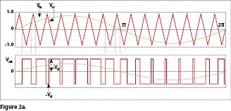
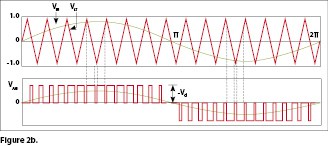 The operating principle involves a triangular voltage wave (the carrier) intersecting with a grid-synchronised sine wave.
For the unipolar mode, a 180° phase-shifted sine wave is generated in addition. Carrier and sine waves are generated in the control circuitry of the inverter.
The unipolar modulated inverter has smaller current ripple then the bipolar one, and thus requires smaller smoothing inductors.
It is therefore a popular choice for solar inverters. However it exhibits higher common mode voltage and this can result in high leakage currents. These arise because the PV panels have significant parasitic capacitance to earth. The leakage current path is shown in Figure 3.
Leakage current
In July 2010 there was an incident in Queensland in which a home occupier got a shock from a ladder leaning against the gutter of his house.
Safety testing did not reveal any fault, and the conclusion was that the array capacitance was coupling leakage current into the roof and onto the ladder via the gutter.
Overcoming leakage problems is very much a subject of topology, but first let’s consider ‘freewheel current’ which is the primary contributor.
In Figure 1, diodes are connected across the switches representing transistors (eg: IGBT types).
The diodes feed the freewheel current back into the DC link capacitor and PV panels. The freewheel current flows because of inductive kickback when switches open, thus building up common mode voltage at the PV panel and therefore leakage current back to earth through the parasitic capacitance of the PV panels.
Tests have been conducted in Australia, indicating that currents of 30mA or more are quite possible.
There are three main ways of dealing with the leakage current:
- interposing a high-frequency transformer (basically part of a switched-mode DC to DC converter);
- isolating the DC link by transistor switches in lines supplying the inverter; and
- providing a neutral voltage point on the PV supply (eg: through the use of capacitive dividers).
Some of the schemes are shown in Figure 4.
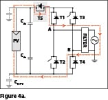
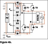
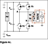
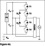 The HF transformer version (not illustrated) has very low inter-winding capacitance, thus isolating the PV panels. The trick is to achieve low leakage while holding construction costs down by reducing the number of components.
In Figure 4a the H5 topology is shown (note: this is patented technology).
The inverter switching pattern is based on unipolar modulation whereby T1 is closed for one half-cycle, and T2 is closed for the next half-cycle – with T3 and T4 being the ‘within half-cycle’ modulating switches.
The important difference with the H4 circuit is that the PV isolating switch (T5) operates in unison with T3-T4, thus isolating the PV panels from freewheeling current.
During the freewheeling phase there are two paths for this current. During the positive half-cycle the current flows through the T3 diode and closed switch T1. During the negative half-cycle, the freewheel current flows through T3 and the diode of T1.
In the circuit 4b, sometimes referred to as ‘full H’, T1 and T4 switch at grid frequency with T5-T6 and T3-T2 being switched at high frequency. PV isolation is achieved, but the component count is high.
Figure 4c shows the HERIC (highly efficient reliable inverter concept) topology. Note that in this circuit the PV panels are not isolated. However, the freewheeling path has been cleverly instituted by T5 and T6 across the output of the inverter.
During the positive half-cycle T6 is closed, and T5 closes during the negative half-cycle.
T3 and T2 switch on alternately for the positive and negative cycles respectively.
T1 and T4 switch at high frequency to provide pulse width modulation.
The T5-T6 and diode combinations confine the freewheel current to the output circuit.
The last schematic shows the neutral point clamp (NPC) circuit.
T2 is on during the positive half-cycle and T3 is on for the negative half-cycle. T1 and T4 switch at high frequency.
The freewheel path during the negative half-cycle is via T3 and D6, and conversely through D5 and T2 during positive half-cycles.
The capacitive divider provides an almost constant common mode voltage, thus reducing the possibility of PV leakage current.
There are many more topologies, but manufacturers don’t provide much information on this subject.
Efficiency considerations
Inverter efficiency is determined by power loss in the switching transistors and diodes.
The fewer switching components the better off you are – but, as with all rules, the proof of the pudding is in the eating.
Thus the full H (4b) inverter has the highest losses, whereas H5, HERIC and NPC are substantially lower and close to one another.
How important is efficiency? Based on a 20-year life, the opportunity cost of one percentage point could be in the order of $16,000. This is in some ways simplistic, the assumptions being a system with average power of 2kW over six hours per day and at 18 cents per kW/h.
Inverter efficiency is a matter of weighting the efficiency levels at various percentage loadings so as to provide a balanced picture. There are two accepted ways of specifying inverter efficiency: the European weighting and the California Energy Commission (CEC) weighting.
Percentages shown in subscript are of the inverter’s rated output. In practice, factors such as dirt and grime build-up, overshadowing, localised heating of the panels, etc, are likely to swamp energy efficiency considerations of only the inverter.
Power factor (if not unity)
Before letting go of freewheel current, we need to look at power factor.
Although there are exceptions, inverters usually operate at unity power factor for the obvious reason that they are controlled in essence by grid voltage. Thus the inverter switches current in phase with the grid voltage.
So what happens to loads requiring reactive current? Well, that’s supplied by the grid.
Think for a moment about an inverter as used in a variable-frequency drive supplying an induction motor. The reactive current of the motor is fed back to the DC link via the diodes, but that is for an ‘isolated system’.
Power factor is becoming very important. As explained above, a grid-connected inverter is a unity power factor device. From October 1, 2015, Energex in Queensland will make it mandatory that every solar power inverter greater than 3kW in size has reactive power control set to 0.9 lagging.
This has been introduced to minimise over-voltages on the electricity network. It will also reduce nuisance tripping of solar power inverters and interference to other customers in the local area.
The Energex requirement will mean an increase in the rating of inverters (3kW would become 3.33kVA).
Power factor, like spinning reserve, is an increasing headache for generation, transmission and distribution people. Percentage-wise, they have to supply more and more reactive load as rooftop solar pushes more and more kilowatts into distribution system.
When connected to reactive loads, isolated inverters ‘automatically’ cope with them, as does the inverter for a motor drive. Grid-connected inverters can have less than unity power factor, and some are capable of providing leading as well as lagging power factors.
The basis for power factor control seems to be a feedback mechanism. The output current phase relationship to grid voltage is measured (by way of voltage drop across a small impedance in the line/s) to the grid connection point, and this is compared with the sinusoidal voltage producing the pulse width modulation in conjunction with the triangular carrier signal (Figure 2).
Maximum power point
Operating at the MPP is what it is all about, and not much is published by manufacturers ‘save that it works’.
Extracting maximum energy from an array of PV panels is based on some sort of strategy. The perturb and observe (P&O) method increases the voltage a bit and checks whether the current goes up a bit. If so, the voltage goes up some more (and so on) until the incremental current is downward.
This method is also referred to as ‘hill climbing’ because of the shape of the power-voltage curve of solar panels. Converted into a firmware algorithm, it is the guts of an MPPT. Note that there are a number of methods, including a conductance method.
MPPT circuitry uses the DC-to-DC converter, an electronic circuit that converts a source of direct current from one voltage level to another. It is a class of power converter.
Electronic switch-mode DC-to-DC converters operate by temporarily storing input energy then releasing it to the output at a different voltage and current. Just like a transformer, they essentially just change the input energy to a different impedance level.
So, whatever the output voltage level, the output power all comes from the input; no energy is created in the converter. A block diagram of an MPPT is shown in Figure 5.
 Essential to the operation of an MPPT is a buck-boost DC-to-DC converter. This circuit can increase the panel voltage or decrease it depending on the switching duty cycle of a transistor switch.
One form of buck-boost is the single-ended primary inductor converter (SEPIC). It is shown diagrammatically in Figure 6 presenting an input resistance that varies with pulse width modulation of the transistor switch S.
 Maximum power from the solar panel is transferred when the source resistance of the panel is equal to the input resistance of the converter. By adjusting the duty cycle the input resistance can be made to match the source resistance of the solar PV panel or array.
The SEPIC converter can step up and step down input voltage while maintaining the same polarities for both with respect to ground.
When the switch S is closed, the inductor L1 builds up a magnetic field, whereas the second inductor L2 is ‘charged’ by the coupling capacitor C. When the switch S turns off, L1 and L2 feed current to the RC load circuit.
By modulating a small AC signal on top of the switching frequency, and comparing the AC voltage and average panel voltage, the maximum power point can be located.
Inverters and more inverters
The Clean Energy Council (CEC) lists about 400 approved grid-connected inverter models, and our listing of a dozen manufacturers is a drop in the bucket.
However, armed with a bit more knowledge, you should be in a better position to ask questions of suppliers.
Features such as communication are important, although not dealt with here. Given that the basic technological requirements are met, other features such as IP rating, weight, information display, etc, may rank higher.
What should you look for in addition to reliability, good documentation and availability of service?
Electrical Connection does not recommend one set of specifications over another, simply offering some general observations.
We think the salient points are MPPT operating voltage range, number of MPPTs and power factor control.
A larger voltage range allows more panels to be placed in series (CEC limits the maximum voltage to 600V DC), this being preferred to paralleling. Two MPPTs or more will allow panel arrays to be better distributed for maximum insolation. Power factor control is also likely to be increasingly important.
To have a look at a comparison guide to what the market offers, click here.
-
ADVERTISEMENT
-
ADVERTISEMENT


