Microgrids: Generation ex
The argument that large baseload generators are here to stay is weakening, writes Phil Kreveld.
It’s often said that we cannot live without thermal power, we will always need synchronous power and there can be no stability without baseload.
They are statements of fact only insofar as we are not prepared to accept substantial re-engineering of electrical power generation and delivery systems.
Such re-engineering is required for microgrids, but the technology is well established.
ADVERTISEMENT
In the following material we go into some detail regarding synchronous generators because of their advantages, which can be summarised as follows:
- an ability to provide lagging and leading current as demanded by loads;
- synchronicity through power-speed governors regulating steam, water or gas to turbines; and
- the power is dispatchable, whenever needed.
For wind and solar photovoltaic (PV) generators those benefits have to be ‘engineered’, and this means somewhat complex solutions.
- They lack the natural ability to provide lagging and leading current – and synchronicity in a system with many generators requires considerable engineering effort.
- The power is not dispatchable unless combined with energy storage.
However, the advantages include:
- rapid response to power changes demanded by loads; and
- smaller unit power sizes allow economic deployment close to power consuming loads.
Rapid response to load changes thus requires energy storage, for example, a battery, to be part of the generators.
In large power systems such as the national electricity market (NEM), electronic power converters for wind and solar often act as slaves, reducing the load needing to be generated synchronously.
In microgrids, electronic power converters can provide voltage and frequency ‘forming’ tasks.
Synchronous systems
The speed of the generators – whether driven by steam, water or gas – is controlled by governors.
In principle, frequency and power have a direct relationship readily explained by the mechanical analogue of driving a car in hilly terrain. As the vehicle travels uphill, it slows unless the accelerator is pedal is pressed. The opposite takes place going downhill.
A synchronous power system has a number of synchronous generators sharing the load, with their rotors running at the same speed. Apart from those separated by long transmission lines, they are in phase with each other.
In Figure 1, the phase (orientation of the rotor) concept is illustrated for two generators connected to a power station bus.
By virtue of the very low impedance offered by the bus compared with the network to more distant loads, the phase (‘voltage angle’ or ‘power angle’) of the generators is identical.
Let us assume that the Unit 1 generator in Figure 1a speeds up, therefore assuming more load and relieving Unit 2 of some load.
Unit 1 draws more current, thus causing increased armature reaction and, as would happen in motors, more torque is provided by its turbine.
The Unit 1 rotor was speeded up ahead of Unit 2 and consequently the Unit 1 rotor is ahead by a small angle, d, thus causing a phase shift in voltage. The voltage of Unit 1 leads slightly.
As shown in Figure 1b, an additional current will flow, adding to the Unit 1 load and reducing the Unit 2 load (it sees the current as a negative contribution), causing Unit 2 to speed up.
However, because we have a synchronous system, the speed governors must maintain speed for the entire system, so Unit 1 is now supplying more power than Unit 2 with total power output matching the load requirements.
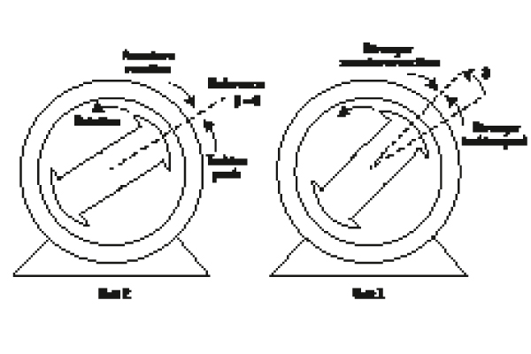
Figure 1a: Unit 1 receives more power from its turbine and its rotor pulls ahead of the Unit 2 rotor.
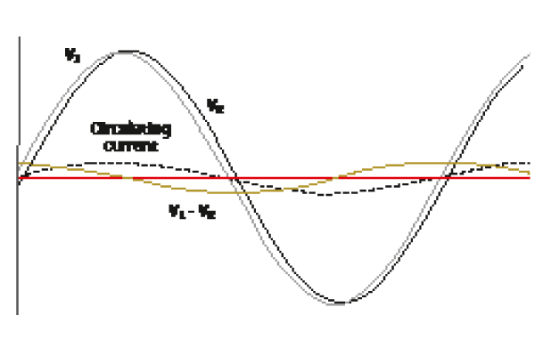
Figure 1b: The Unit 1 rotor is slightly ahead, as is its voltage V1 with respect to V2 of Unit 2. Subtracting V2 from V1 provides a sine wave of the same frequency. Because of the short distance between the generators, the link impedance is purely inductive, so that the circulating current between the two generators is lagging by 90°.
The means of maintaining frequency while changing power sharing between generators is a unique feature of synchronous generator systems (assuming that the combined load equals the combined generated power).
With respect to ‘quadrature’ (lagging or leading) current as required by the load, a somewhat similar reasoning can be adopted. However, rather than turbine power, excitation current of the rotors is involved.
Leading current causes field strengthening, requiring voltage reduction, and the opposite takes place with lagging current.
In the above example of two generators on a common bus, the voltage regulators balance out the quadrature current required by the load.
The high level of rotational inertia makes sharp changes in frequency impossible. A sudden increase in load causes the armature of a synchronous generator to be pulled back, experiencing a braking torque, against the direction of rotation.
But, because of inertia, the frequency barely changes for as long as six or more cycles. In this interval the speed governor allows more steam, gas or water to provide the power to restore speed at the synchronous level (50Hz).
Legacy and new systems
Photovoltaic (PV) panels generate DC and this is inverted to AC for connection to the grid.
Wind turbines are asynchronous machines requiring conversion to DC and from there to AC in order to be connected to the grid. Power conversion is achieved electronically by means of fast switching transistors, decoupling the primary source of energy from the grid. In other words, there is no natural inertia.
In contrast to the grid-tied solar inverters on roofs, in isolated networks without a native synchronous machine source, at least some of the inverters must maintain voltage and frequency stability.
The mechanisms for this are based on some form of droop control as shown in Figure 2.
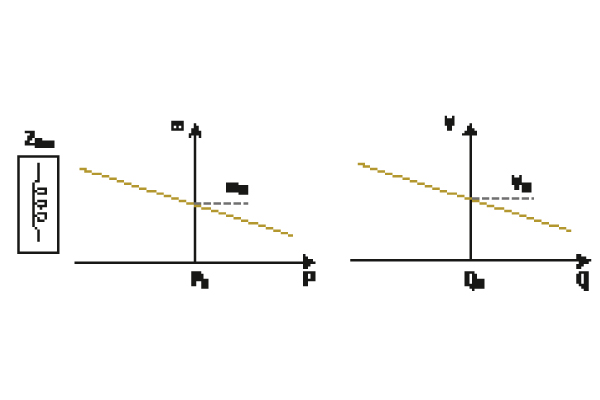
Figure 2: Droop control for synchronous generators featuring a lagging load (the usual case). The left graph shows the relationship between power, P, and generator speed, w. The more power required from the generator, the lower the speed. P0 is the power providing synchronous speed, w0. The right graph shows the relationship between reactive power, Q, and voltage, V. The bigger the lagging reactive load, the lower the voltage. At the system voltage, V0, the reactive load the generator can support is Q0.
In a conventional network with only synchronous generators participating, individual generators provide the appropriate power and reactive power at the network frequency and voltage as determined by their droop characteristics.
If this seems a little confusing, imagine a power network being established from a ‘black start’.
The frequency support generator starts up and – once it is running at a stable synchronous speed – a larger power generator is connected to the generator bus. Then the next one is connected, so that in due course the complete power supply to the network is established.
Every generator coming on line is first synchronised (voltage, frequency and phase being adjusted to that of the bus), and in that manner supplies power in accordance with its droop characteristics.
Powering up a large network cannot be done quickly, as the synchronisation process is a sequential one. The load is also being switched on to generator buses in steps small enough that generators already connected do not become unstable (dropping out of synchronism).
The grid-tied inverters receive their frequency instruction from the grid. The voltage is ‘what it is’ at the point of coupling to the grid, and the only controlled variable is the current supplied by the inverters to the coupling points.
The frequency of operation of the inverters is controlled by means of a phase locked loop (PLL), which ensures that the inverter’s inbuilt oscillator marches in synch with the grid frequency. The PLL principle is explained in Figure 3.
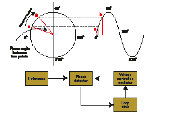
Figure 3: Phase locked loops are essential in keeping inverters supplying power to the grid at grid frequency. Points a and b can refer to two sine waves. Provided the angle q (between a and b) remains the same, both sine waves have the same frequency.
Note that a change in phase is a change in frequency because a sine wave has the formula of 𝐴,sin–𝜃., where q is the instantaneous phase equal to 2𝜋𝑓𝑡, f is frequency and t is time.
A sudden change in q (meaning that t has not changed) implies that f, the frequency, changed. Changes in phase can cause instability in distribution networks with no synchronous generators.
Moving on
The grid-tied inverters of millions of solar PV systems can be part of a microgrid but only as ‘prosumers’, and not as independent generators.
There are ‘voltage forming’ inverters that can establish voltage and frequency for microgrids. Grid-tied inverters only push out current at whatever the grid voltage is, relieving power required from voltage-forming inverters and supplying power needs at their local installation sites.
Microgrids by their very nature are likely to be low voltage, or perhaps medium voltage. Unlike the high-voltage transmission system, which has largely inductive impedance, microgrids are usually far more resistive than inductive. This has important implications for connected generators, whether synchronous or asynchronous.
On the high-voltage side of power distribution, conventional synchronous generators adjust their excitation current of the rotor DC field current windings to provide the required reactive power of the network.
As is evident from the article on inverters in this issue, the natural ability of synchronous generators to supply reactive power is a big advantage. In the case of inverters, relatively complicated circuitry can be required to provide this capability.
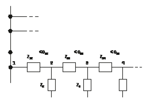
Figure 4: A line diagram of a distribution system with voltage-forming inverters at the nodes. Each generator has its own voltage angle, although in a stable situation there is little difference between individual angles. A sudden load change at a node can bring about a change in voltage angle and cause other generators to try adapting via their phase-locked loop circuits.
Microgrids, in principle, can operate without a ‘primus inter pares’ (a first among equals). However, a collection of voltage-forming inverters of equal power can suffer from voltage and frequency swings that may not be tolerable for connected loads such as induction motors, etc.
Technical literature cites examples of basic support by diesel generators which, although not capable of servicing the power requirements, are large enough to form voltage.
Note that there is no absolute need for a synchronous generator. A large battery-supported inverter source can be used, and can even be used for ‘black start’ conditions.
In Figure 4, an important point is made about networks and the relationship with generators.
Generators placed at the ‘nodes’ have a voltage angle as indicated. Changes in load cause changes in the voltage angle, and a change in angle is a change in frequency while the angle is increasing or decreasing.
The rate of change of frequency has to be contained within tight limits for stability purposes. Without a dominant voltage former, a process of ‘hunting’ between the inverter PLL circuits can occur, leading to instability.
Grid reconnection
Microgrids that can drop out and reconnect to the grid offer great security advantages, but this is not a simple exercise.
In the foregoing text the tacit assumption was that generators between them ‘sort out’ the stability of the network.
As we saw for a synchronous generator network, the ‘black start’ example operates on a strictly sequential basis whereby generators are added to the system, each in turn being synchronised to the growing generated power base.
As such, no communication between the generators is necessary. In practice, power stations work with forecasts and receive despatch commands from some central authority (eg: the Australian Energy market Operator), and this happens via a communication network.
A microgrid reconnecting to the grid cannot be ‘brought up to speed’ as would be done with a synchronous generator. In practice, a communication/control network is necessary.
The control protocol would disconnect non-essential loads then select a large generator or several voltage-forming generators. The frequency, phase angle and voltage conditions of these would be judged to be within an acceptable tolerance with the grid before the reconnection circuit breaker was closed.
Conclusion
In 50 years or so, no more than two investment cycles in baseload generation, will we still see high-voltage transmission grids and large baseload plant?
Or will there be growth in smaller nuclei of power generation in or close to population and industry centres? We call these microgrids today, but that term might have disappeared by then.
What about our fixation with alternating current or constant frequency? Appliances of the future capable of operating within larger frequency tolerances might be a natural consequence of the drift to decentralised power generation.
Direct current for stepper motors, rather than today’s workhorse – the squirrel cage induction motor – may allow an almost direct use of solar PV power.
Hydrogen fuel cells, rather than electrochemical batteries, may be a main form of energy storage, and the NEM might well have disappeared.
-
ADVERTISEMENT
-
ADVERTISEMENT

