Generating interest
Generator technology and installation are specialty areas, but contractors can benefit from some understanding. Phil Kreveld explains.
Complications that arise from the installation of standby generators and autonomous generation are mainly due to the alternating current ‘legacy’ system.
This kind of system is well over a century old and it still dominates global electricity supply.
ADVERTISEMENT
Technical issues crop up particularly when generators are also required to function ‘behind the meter’. This is called distributed generation by network service providers.
Generation types
Standby plant in its simple form can take seconds to switch in after mains power failure and is therefore unsuitable for most commercial and industrial applications.
Autonomous plant (grid independent) is generally not economically feasible other than for large remote operations: mining, refining, ship loading, etc.
Distributed generation (DG) can fulfil the tasks of standby. It is also able to reduce energy demand from the grid – for example, peak demand shaving – and this has economic benefits for many larger consumers in the mega volt-amp (MVA) range.
Uninterruptible generation is a further refinement. In practice, it is a basic requirement for mission-critical installations (hospitals, IT, defence, etc).
Battery supported uninterruptible supply (UPS) systems require generator back-up for extended mains failures.
The diesel rotary uninterruptible power supply (DRUPS) obviates the use of batteries other than for ancillary tasks such as engine starting.
A DRUPS system comprises a diesel engine and synchronous motor/generator energy-storing flywheel inline assembly, energised by the grid during mains availability.
When mains power is interrupted an electro-magnetically coupled clutch transfers the flywheel kinetic energy to the synchronous motor/generator (now in generator mode). This allows time for the diesel engine to start and reach the speed required to power the generator.
The combination of standby generation and an inline battery backed UPS system is powerful, as it provides smooth power transfer.
Also, when mains power is restored, there are several options. One is the use of automatic transfer switches to supply mains power and/or to employ the inline UPS to supply other parts of the load to server rooms, etc.
Synchronous generator
This will probably be a four-pole machine. The relationship between speed, N (in revs/minute), frequency, f (Hertz) and pole numbers, P is given by:
?=,120?-?.
Thus, for a four-pole machine and a frequency of 50 Hz, N is 1500 revs/minute, which is a standard speed for diesel engines.
Voltage is generated by the magnetic flux from the pole windings on the rotor, cutting the phase winding conductors housed in stator slots.
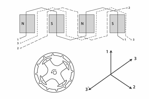
Figure 1 shows the bare essentials of a three-phase machine. (Note: the phase windings occupy what we can term electrically 180°, equal to the pitch of a pole pair.)
Phase 2 is separated from Phase 1 by 60° but, being reverse connected, is actually at 120°. Phase 3 is in the correct 120° relationship with respect to Phase 1 (refer to the vector diagram).
The flux distribution in the air gap is close to sinusoidal, so that harmonics in the generated voltage are low, typically 3% or less.
However, the load current drawn by LED lighting, variable-speed drives, IT equipment and other ‘electronic front-end’ equipment will have a much more pronounced effect on the installation’s voltage when supplied by the generator than when the installation is connected to the mains.
The standby generator takes the place of the grid but does not have the stiffness of the grid. As a supply, the generator has a much larger short-circuit impedance than the grid.
Consequently the connection of large loads approaching the capacity of the generator must be carefully planned. Motors pose a problem in several ways: inrush current on starting, and reconnection after a power interruption.
In some installations serviced by a stiff supply, motors can be started without having to observe a sequence. In other words, the problem arises only on standby power.
Typically the transient reactance of a moderate capacity generator (about 100kVA) is 12% or more, well over four times greater than a nearby distribution transformer. As a consequence, induction motors simply might not ‘get away’, remaining in the locked rotor position until thermal relays pop.
The period of switchover to standby, and switch back to mains, can be critical for large motor loads. During this interval, back electromotive force reduces and phase angle lag increases.
Therefore reconnection can cause very large currents to flow, requiring the use of ride-through relays, disconnecting motors after a safe reconnect time limit has expired.
Basic generator controls
Frequency control is provided by engine governors: mechanical, hydraulic, electrical or a mixture.
The action of centrifugal force on a set of weights is central to the operation.
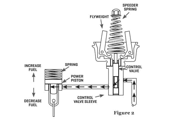
Figure 2 illustrates the basics. As is evident, centrifugal force exerted by the weights is counterbalanced by a spring controlling a sliding fuel valve.
As speed diminishes, the weights move inwards, compressing the spring and admitting more fuel. When speed exceeds the required value, the weights become more horizontal and the spring acts on the fuel valve to cut back supply.
Voltage control is provided by varying the excitation current to the rotor. In principle, all forms of excitation control work the same way, but there are practical differences.
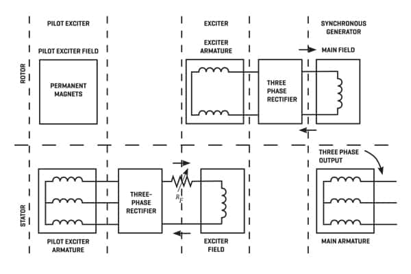
The brushless form of excitation does not use slip rings, removing a source of mechanical wear and tear.
Figure 3 shows the basic structure. A small shaft-mounted generator winding supplies a full wave rectifier providing DC current to the rotor windings. (Note: the magnetic field control for the small generator is stationary and can derive current from a battery.)
In this case the voltage control will be part of the stationary frame of the generator.
Under load fluctuation, the synchronous generator varies its speed, and this needs to be kept within a tight range.
Under equilibrium conditions, torque x revs (engine input power to the generator) is balanced against the volt-amp output of the generator.
Basically the engine torque is counterbalanced by the electrical torque of the generator. A reduction in power requirement from the electrical loads results in momentary acceleration of the rotor and thus a frequency shift.
The rate of change of frequency depends on the moment of inertia of the engine rotor. In large synchronous machines of about 100MVA the resulting time lag can be several seconds (some hundreds of cycles). It is the very property of inertia that provides stability to the generator-grid system.
Frequency control
In standby operation, isolated from the grid, the generator operates in isochronous mode, that is, in constant frequency mode.
This seems a little obvious, having established that the engine governor is there to keep speed/frequency constant. However if several paralleled generators were supplying the load, then the droop method would be employed to allow load sharing.
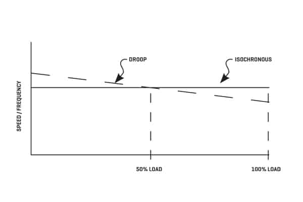
The droop method (Figure 4) establishes a linear relationship between power output and speed, so that the correct frequency is obtained at the required output.
As shown, at no load the speed/frequency will be higher, between 3% and 5%. (Note: this is precisely determined by the control system of the generator.) In a practical situation, the load share fractions between paralleled generators is determined by their individual droop characteristics.
Imagine a plant with two synchronous generators. On start-up, the first generator will be governed by the isochronous mode and will therefore supply the entire load. The second generator is started but functions in droop mode and will eventually supply 50%.
The best way to picture the process is by way of manual control.
The plant operator starts the second generator on no load, observing frequency and phase, and when synchronism is established, closes the generator breaker.
The operator tries to incrementally raise engine speed but, because of the droop characteristic of the generator, it assumes a small amount of load. Further attempts to increase engine speed will move the load percentage operating point to the right (refer to Figure 4).
If a generator were connected to the grid in isochronous mode it would become a synchronous motor (its natural load share by comparison being minuscule). Only in droop mode could it fulfil its function as a supplier of energy, however small by comparison.
If a limited number of nominally equal capacity generators were paralleled in isochronous mode, frequency hunting instability would result.
Leading and lagging power factor
For a better understanding of synchronous generators it is helpful to look at their vector diagrams.
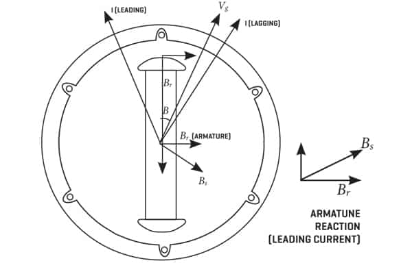
The voltage generated under open circuit conditions is in phase with the magnetic flux vector Br of the rotor. For convenience, the flux is assumed to be concentrated in a single vector, without spoiling the argument. (Refer to Figure 5a.)
In Figure 5, the generator is supplying load current and generating an ‘armature reaction’ flux component due to the current. The current distorts the field provided by the rotor.
The vector, Emax in Figures 5 is not observable except when the generator is open circuited.
As can be seen, the armature reaction flux Bs is in quadrature with the load current and has a component in line with the rotor flux (but reducing it, as it is in opposition), and a component in quadrature with the rotor flux Br which tends to pull the rotor against the direction of rotation.
The resultant flux Bt is responsible for the terminal voltage V and has an angle d with respect to Emax.
The torque provided by the diesel engine prevents the rotor from lining up with Bt – it can be pictured in mechanical terms as a twist in a shaft under torque.
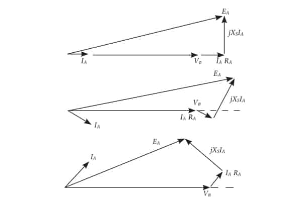
Figure 6 provides scenarios under unity, lagging and leading power factors. As will be seen, leading power factors pose a problem.
The equivalent circuit, shown on a per-phase basis, indicates resistance and inductance of the stator. The inductance is the virtual inductance of armature reaction and the leakage inductance of the stator winding.
In Figure 6 the generator diagram for a leading current is shown, and instead of there being a flux component to reduce the rotor field, it is now being added to.
Under lagging current, the voltage regulator adds more field current to the rotor in order to maintain voltage. Under leading current, the voltage regulator has to reduce excitation, reducing field current, and is much more likely to run out of range. As flux weakens, pole slipping can occur.
In applications where passive line filters are employed, for example, fifth harmonic traps, reduced starting voltages may be necessary because of a large leading power factor. Otherwise, the filters may require isolation during generator start-up.
Summing up the basics: engine speed control provides real power control (kilowatts) as was seen in the droop characteristic explanation.
The role of voltage control, in effect, is to control reactive current. The circulation of reactive current between the two generators should be avoided, and the automatic voltage regulator adjusts excitation for this purpose.
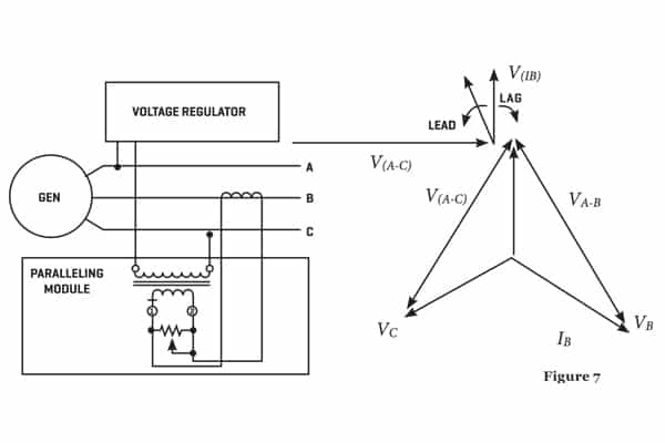
In Figure 7 a simple scheme is shown for achieving control of reactive current. The current transformer, as indicated by the accompanying vector diagram, develops a voltage across its burden which, for a unity power factor load, is in quadrature with the line voltage.
As can be seen from the dotted lines, the burden voltage vector swings in an anti-clockwise direction for leading power factor and in the opposite direction for lagging power factors. This determines field excitation change in order to provide the kVAr required by the load without reactive current circulation between the generators.
Unsurprisingly, the business of controlling generators is benefiting from microprocessor ‘smarts’. In multi-generator plants, this is inevitably the case.
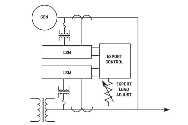
However, the basic control is the load sharing module (LSM) which, for example, can be employed in demand peak shaving.
Figure 8 shows an arrangement for a single generator with connection to the grid. The LSM operates on both the AVR and engine speed control, taking care of kilowatt and kVAr control. A programmable logic controller (PLC) facilitates intelligent control.
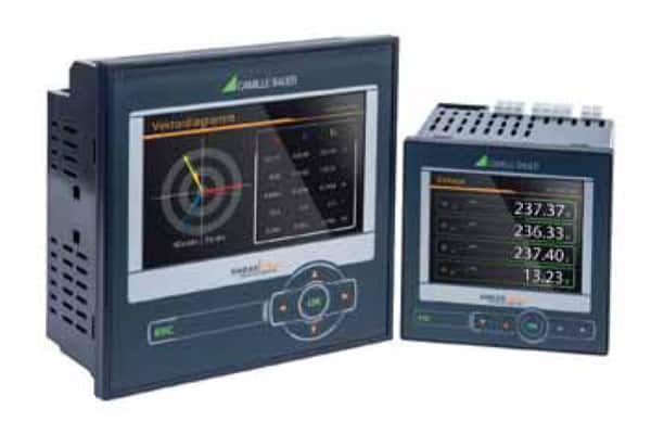
In addition to specialised instrumentation, the use of smart panel meters for small installations can provide the necessary controls as in Figure 9. This shows a power meter-PLC combination using ECOSYS, an open system suitable for a broad range of control applications.
So far, the diesel engine has been left out of the picture. Apart from regular maintenance, inspection of the starter system and battery health, exercise under load is important. This applies very much to ‘standby only’ engines.
Running the engine generator off line at regular intervals – using a resistive load bank or combination lagging power factor load bank – guards against wet stacking, or unburnt fuel in cylinders.
It is hard to predict how important the role of standby generators will be for industry and commerce. The current uncertainty in security of supply is real, although subject to exaggeration in the popular press. For many businesses it can result in severe losses.
Although generator technology and installation are specialty areas, now is the time to take a professional interest in the technical side.
-
ADVERTISEMENT
-
ADVERTISEMENT

