Fibre optic connectors: the make or break of a network
Optical fibre connectors are used to join optical fibres where a connect and disconnect capability is needed. The connector terminates the end of the optical fibre, and then mechanically couples with another connector, aligning the fibre cores so that light can pass through with little or no loss. Continuing research and development has resulted in the market release of over 100 differing fibre connectors since the mid-1980s, but they all contain four central elements.
The ferrule is a long, thin cylinder through which the optical fibre is threaded. In a connection, two ferrules physically touch, allowing the fibres to be accurately aligned and mated. Typically of metal or ceramic construction, the end-face of the ferrule can be polished to a convex shape, that allows the fibres to physically touch when mated together. The end face of the ferrule may also be polished with an 8 degree angle to further reduce reflection (high return loss).
ADVERTISEMENT
The ferrule sits inside the connector housing, constructed of metal or plastic, which serves to make the connector easy to handle, and keeps the connector firmly attached within a connection.
The cable attaches to the connector housing and is the point of entry for the fibre. Typically a strain relief boot is added over the junction between the cable and the connector body, providing extra strength and protection to the junction.
Optical fibre connectors do not use the male-female configuration common to electronic connectors. Instead, a coupling device such as alignment sleeve is used to mate the connectors. Similar devices may be installed in fibre optic transmitters and receivers to allow these devices to be mated via a connector.
The original mass-utilised straight-tip, or ST connectors, have a bayonet mount and a 2.5mm ferrule, and mate via a mating adaptor. The ST Multimode is a very popular connector used in LAN applications.

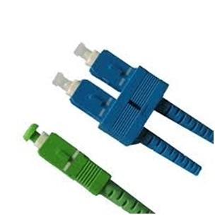
Subscriber connectors (SC) also use a 2.5mm ferrule but have a simple snap-in latch, and are widely accepted in multimode LAN applications.

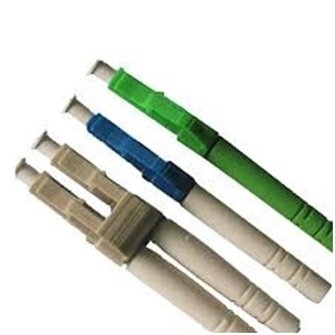
Increasing demands for higher density applications drove the development of small form factor (SFF) connectors, the most successful of which has been the local connector, known as LC. The LC uses a smaller ferrule of 1.25mm, allowing more fibre ports per unit of rack space.

The high density demand soon resulted in the development of multi-fibre push on connectors (MPO). Based on the single ferrule technology, MPO connectors are used with ribbon or mini-round cable and can provide up to 24 fibre connections in a single connection point. MPO connectors are commonly used in data centre cabling systems in conjunction with LC fanouts.

Different connector types have different characteristics, different advantages and disadvantages, and different performance parameters. In general, a good connector should:
Cause little or no loss of optical power across a junction point (low insertion loss and high return loss)
Be easily and quickly installed
Be able to be connected and disconnected many times without changes in loss
Have a consistent and calculable level of loss
While a well engineered connector can minimise loss due to air gaps or misalignment, the reality is that a speck of dust can undo all the designer’s good work. Dust, oil or dirt on the fibre can partially or even totally obscure an optical fibre connection. Dust caught between fibre end-faces as they are pressed together in mating can cause irreparable damage to both fibres. Keeping connectors clean is vitally important – best practice involves cleaning connectors prior to each connection, and using dust caps to protect unused connectors and couplers.
Connectors certainly aren’t the most glamorous element of a fibre optic network, but they can make or break it. So while you’re envisioning the magic that is fibre optic technology, spare a thought for the humble connector, without which, a fibre optic network would just be a mass of glass cables.
|
Common Connector Types |
||
|
TYPE |
TYPICAL
|
APPLICATIONS |
|
ST Singlemode |
0.3 |
Legacy industrial applications, patching and equipment interfaces |
|
ST Multimode |
0.3 |
Legacy industrial applications, patching and equipment interfaces |
|
SC Singlemode |
0.2 |
Telco, Video, LAN’s and WAN’s, angled version for low RL (return loss) |
|
SC Multimode |
0.2 |
LAN applications, patching etc new industry standard in multimode |
|
LC |
0.2 |
SFF – LAN,WAN, Telco, high density networking, data centres and storage networks |
|
MU |
0.2 |
SFF – Telco applications |
|
MPO/MTP |
0.2 |
Multifibre/Array – 40/100Gb Ethernet, datacentre, high density LAN, storage or telecommunications x-connects |
|
Less
|
||
|
SMA |
1.0 |
Obsolete industrial LAN |
|
FDDI |
0.6 |
Obsoleted duplex connector used for direct interfacing to FDDI equipment |
|
ESCON |
0.6 |
Duplex connector purely used for direct interfacing into IBM equipment |
|
FC |
0.2 |
Singlemode telco and infrastructure networks. Angled version for low RL |
|
DIN |
0.5 |
Found on superseded European telecommunications equipment |
|
VF45 Multimode |
<0.75 |
No ferrule SFF connector, LAN, fibre to the Desk |
|
VF45 Singlemode |
<0.75 |
No ferrule SFF connector, LAN, fibre to the Desk |
|
MTRJ |
0.5 |
Superseded SFF LAN connector, LAN equipment interface and fibre to the desk |
|
E2000 Singlemode |
0.3 |
Optical interface found on European telecommunications equipment |
Richard Kaehne has been engaged in the fibre optic industry for over twenty years in senior sales, technical and product management roles. He has been with AFC for over 15 years and is currently their Group Product Manager. Richard also actively participates as a member of the AS fibre optic testing sub committee.
Visit www.afcgroup.com.au.
-
ADVERTISEMENT
-
ADVERTISEMENT

