Do you know what happens when a solar panel is struck by lighting?
Solar panels sit atop our homes or are exposed in solar farms, soaking up as many rays as they can. Phil Kreveld looks at what happens in the unfortunate event of a lightning strike.
In X-Men (2000), Storm famously delivers one of the worst (or best) superhero lines in recent memory: “Do you know what happens when a toad is struck by lightning? Same thing that happens to everything else.”
ADVERTISEMENT
While the quote has gone down in infamy, it’s not exactly wrong, there wasn’t much that Toad (the villain) or a toad (the reptile) could do. There isn’t much anyone or anything can do about a lightning strike.
When it comes to our homes, lightning strikes are dangerous because of their fire risk and the likelihood of wrecking plugged-in appliances. Having solar panels on the roof does not make a dwelling more susceptible to a lightning strike, however, the panels increase the chance of a roof fire.
Australian standard AS 1768 specifies lightning protection measures to be taken for electrical installations and therefore also for solar installations.
The 2021 edition of AS 1768 revises previous editions and aligns more closely with the global IEC standards. To reduce the risk of damage and injuries caused by a lightning strike, AS 1768 includes a risk assessment tool that compares a calculated risk against a tolerable risk level, however, the standard also notes that protection measures may be justified regardless of the outcome of the risk assessment. In addition to meeting AS 1768, solar installations also have to also comply with:
- AS/NZS 5033 Installation and safety requirements for PV arrays
- AS/NZS 4509.2 Stand-alone Power Systems – Design
- AS 4777.1 Grid connection of energy systems via inverters – Installation requirements
- 2 Inverter Requirements
- AS/NZS 3008 Electrical installations – Selection of cables
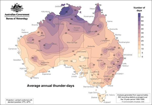
The Bureau of Meteorology map below (Figure 1) indicates the annual number of lightning strikes per year throughout Australia, expressed in days. As to how much attention should be paid to these statistics in addition to concerns about the personal safety of occupants, depends on how repair, replacement and the cost of lost business might be.
Generally, domestic solar systems are covered by house insurance although they increase the premium. Commercial and industrial buildings are insured on negotiable terms. The rooftop placement of PV panels means any fire ignition due to the PV panels or cabling is beyond the building’s fixed fire protection and detection systems. This can result in delayed detection of the fire and consequently, delayed manual firefighting operations. Therefore, lightning protection for commercial and industrial buildings with rooftop solar should be considered.
The map indicates some population centres on the southeast coast as well as Darwin and vicinity where lightning protection is an important safeguard for life and property.
Other than for transformer-coupled systems, i.e. the larger rating ones typically over 100kW, the DC portion including the solar panel array is floating, with only the metallic panel retaining structure earthed.
A lightning strike during daylight hours, resulting in a roof fire poses a hazard for fire crews as the PV panels can have a voltage of 600V or more. Opening the DC isolator on the inverter input does not remove the potential hazard.
The AS 1768 standard specifies the rolling sphere method for lightning arrestors. The principle is illustrated in Figure 2 and as is shown, any part of the structure not touching the sphere is protected. The radius of the sphere can be calculated by various methods. These take into account the electrical current strength of the lightning strike. Below is one such formula.
Rsc is the radius, in metres, of the rolling sphere, and Imax (in kilo amps) is the maximum current of the lightning flash-over. The radius of the sphere is the distance of the flash-over to the lightning leader (see Figure 2).
As the diagram shows, to protect a roof with projections such as chimneys, aerials and dishes, ventilation fans and HVAC machinery, the larger the sphere radius, the higher the arrestor has to be so that nothing on the roof makes contact with the rolling sphere, whose various positions are shown in dotted outline. Level III is considered adequate for domestic applications.
TABLE 1
| Protection level | Current (kA) | Rsc (m) |
| Level I | 3 | 20 |
| Level II | 5 | 30 |
| Level III | 10 | 45 |
| Level IV | 16 | 60 |
The other aspect of lightning protection is guarding against ‘imported’ voltage disturbances and that opens up the science of grounding and surge suppression devices. Most of these matters are not covered by mandatory standards, although AS/NZS 5033 makes reference to surge protection devices.
The induction of high-voltage pulses can be the result of nearby strikes. In Figure 3, the basics of induction are illustrated.
To determine the effect on a wire loop, the mutual inductance between the lightning current conductor and the loop must be computed. Below is the equation for a rectangular loop, as might be the case for a string of panels. Note that the plane of the rectangular loop is parallel to the lightning current conductor, therefore providing for maximum magnetic flux linkage. Were the above loop situated on a roof with a pitch of 30°, flux linkage would be halved, as would the induced voltage.
M is the mutual inductance in Henrys, m0 is the permeability of air, approx.,
1.3 x 10⁻⁶, L, W and D are in metres. Doing the maths with W, D and L all 1m, yields a mutual inductance of 0.14 micro henrys. The voltage that can be induced in the rectangular loop is:
The rate of change of current, DI can be enormous, for example, an increase of 3kA in one microsecond is a DI/Dt of 3000/ x 10-6, i.e., 3,000 million amps/sec. Given the calculation for the mutual induction of 0.14 micro henrys, the peak induced voltage would be 0.14 x 10-6 x 3000 x 106, or 420 volts. At level IV, i.e. 16 kA, the induced voltage would be 5.3 times higher, i.e., 2.2 kV.
In cases where a lightning arrestor protects the building, earth resistance generally cannot avoid the occurrence of dangerous step potential, and neutral surges so for interconnected buildings, an earth mat need be constructed to provide a close to common ground voltage. Even from several hundred metres away, lightning currents can also cause dangerous surge voltages in conductor loops, through either capacitive, inductive or galvanic coupling.
Large surge voltages can be coupled over a radius of several kilometres. The international lightning protection standard IEC 62305 describes how direct lightning strikes of up to 200kA may be safely arrested. The current is coupled into the earthing system and, due to the voltage drop at the earthing resistor, half of the lightning current is coupled into the internal installation. The partial lightning current then divides itself among the power lines entering the building (number of cores of power line entering building), while around 5% enters data cables.
As shown in Figure 4, surge protection devices should be installed at the DC link side of the inverter and at the point of coupling, (i.e.: the AC side in the switchboard) for appropriate protection.
The metal oxide varistor (MOV) is probably the most popular clamping device used for transient suppression. Physically MOVs consist of millions of tiny semiconductor junctions (PN junctions) that act as diodes with larger forward voltages. A common material for MOVs is a granular form of zinc oxide, sandwiched between several parallel electrodes. The MOV is inherently suitable for AC voltages as the diodes are disposed of in all directions. As the voltage across the MOV rises more and more of these diodes turn on with the result being, in effect, a non-linear resistance that reduces incrementally with increased voltage. This is precisely the effect needed to clamp excessive voltages on the device being protected. Operation as a clamp requires effective voltage division. At line voltage, the MOV is essentially an open circuit but as the voltage rises, the differential resistance DR, which is equal to DV/DI decreases. Thus, provided the impedance of the upstream circuit to which the MOV is connected is higher than DR, voltage division will lower the transient voltage. However, MOVs have a high let-through voltage; that is to say that the voltage across the device continues to rise with input voltage albeit at a much-reduced rate because of the low DR.
Silicon avalanche diodes (SADs), on the other hand, have a sharply defined clamping voltage (being the point where the reverse biased diode junction breaks into avalanche mode with reverse leakage current suddenly increasing by orders of magnitude). The DR of the device is then a virtual dead short, and the voltage is clamped at the avalanche point (i.e.: no let-through voltage effects). In comparison to MOVs, SADs have a much-reduced energy dissipation capacity and are therefore not usually used on power circuits.
The faster the rise time of an impulse, the broader its frequency spectrum is. Filters constructed from inductors, capacitors and resistors can be very effective transient suppressors. The low-pass filter can take several forms and represents the standard method of reducing the slew rate of fast transients. The feed-through capacitor in combination with the self-inductance of the leads connected to it forms a low-impedance path to Earth for the high-frequency components (i.e.: those that are associated with the fast rise time of the transient). Figure 5 illustrates an effective filter to protect against transients.
The use of filters and surge suppression devices is, in any event, useful because there can be severe line disturbances, not only caused by lightning, for example, due to the operation of reclosers, rapid changes in load, etc. To minimise induction effects, cable lengths must be as short as possible, e.g., in the direct current (DC) side of the solar system it is possible to reduce the cable length of the positive and negative terminals by twisting the leads together to reduce the cable loop surface. On the alternating current (AC) side, it is possible to reduce the cable length of the protective earth (PE), phase and neutral conductors, by twisting them together so as to avoid unnecessary large cable loops in the system.
-
ADVERTISEMENT
-
ADVERTISEMENT


