A powerful approach to cutting electricity costs

Consumers think a competitive tariff is the only way of cutting electricity costs. Phil Kreveld outlines another way that offers business prospects for contractors.
Reducing maximum demand is the name of the game for power companies.
ADVERTISEMENT
However, some euphemistic phrases are employed, including demand management, flexible demand control and a few more that actually stand for load shedding. At best, there’s a financial incentive to turn the switch off when generation-transmission systems cannot cope.
Irrespective of terminology, kVA demand flattening is now imperative, as it’s the kVA that is killing the electricity system when energy demand peaks.
To ensure that the consumer market understands the importance of this issue, kVA demand charges – usually billed on a monthly basis – are being levied on lower and lower energy users.
Only a few years ago kVA demand charges for consumers using less than 600MW-h a year did not exist. These days, in Queensland and many parts of New South Wales, consumers with monthly bills of $2,000 and more are typically charged $15 to $20 per kVA (1,000 volt-amps) per month.
What’s the problem?
Technically, kVA is called apparent power, and the more that has to be transmitted the more the power lines sag as temperature limits are approached.
Reactive power, kVAr, as more and more is demanded, causes voltage regulation. Boosting transmission line voltage stability is done with synchronous condensers and static var compensators but these are costly investments.
At the distribution level the same considerations apply, although on a lower scale.
The ‘gold plating’ that network providers are accused of is not all due to the oligopolistic squeezing of every available dollar out of consumers.
Network providers have to ensure sufficient investment so that peak demand can be met at acceptable voltage levels. Australia, with its relatively thin population density, has an awful lot of wire per consumer, and that makes demand management all the more important.
However, the Australian Energy Regulator, which approves rates of return on new capital expenditure by transmission and distribution companies, is casting a beady eye on new investment proposals based on maximum demand.
The economist Professor Ross Garnaut says ‘poles and wire’ companies will have to consider other strategies for containing demand peaks.
Although we always talk about power factor, it is actually the reactive factor that is becoming the primary worry of distribution network companies. For a phase angle between volts and amps of ϕ, the power factor is cos ϕ and the reactive factor is sin ϕ, or if given the power factor, the reactive factor is: √1-cos2ϕ
A power factor of 0.85, requires 53% of the line current as reactive component. Little wonder that stricter attention is being paid to power factor correction. Even a respectable 0.95 power factor requires 31% reactive current contribution.
Power factor and kVA
The measurement of kVA demand by digital power and energy meters is a straightforward process and is basically the product of root mean square (rms) current and voltage.
Most installations are four-wire and therefore monitor the voltage by current product in each of the three phases.
Voltage and current rms values include harmonics, as far as can be determined. Therefore harmonics can add to demand. However, at the point of common coupling (pcc) the harmonic voltages are likely to be very low.
An installation with 30% total harmonic current distortion (THID) and harmonic voltage distortion of 3% can indicate a demand addition of the order of 0.9%. Total power factor, including harmonic volt-amps is given by the formula below:
kW
√kVA2 + kVA 2 + kW2
where kW is effective power, and the terms in the denominator are, respectively, reactive kVA and harmonic kVA.
The reactive kVA for most installations is the important figure, and this is where power factor correction (displacement power factor) can make a big difference in the cost of electricity.
Measure first
Quite a few installations have high displacement power factors – often those with ‘electronic front-end’ loads.
As an example, direct on line (DOL) motors can have power factors of 0.8, or lower when under light load compared with their rating.
The same type of motor when supplied by a variable-speed drive with gated thyristor or insulated gate bipolar transistors (IGBT) might have a power factor in excess of 0.9. Power factor correction in such a case will not make a dramatic difference.
A thorough power and power quality survey is generally advisable, particularly where harmonic filters are going to be installed.
In four-wire installations, power factor analysis should be carried out for each phase, and obviously for a sufficient period so that maximums and minimums and their durations can be observed.
Power factor penalties make this essential, as an unforeseen 15-minute or 30-minute lapse in power factor can bring on a kVA surcharge for the ensuing 12 months before the meter reset occurs.
Reducing KVA by power factor correction
The two ways open to power factor correction are capacitive and active harmonic filtering.
Capacitive correction is a tried and true method for increasing displacement power factor. The use of self-healing capacitors, pre-charging, and zero-crossing switching makes this type of equipment a suitable industrial installation choice – but harmonic protection is important.
As a rough guide to determining the possibility of resonance, the formula below should be applied:
Hr = √(MVAsc/MVAcap)
Hr is the resonant frequency harmonic order, and the MVA values are respectively the short-circuit power of the transformer, and the MVA of the capacitor bank (√3 x capacitance per phase).
Chokes in the lines of the capacitor bank are the standard way of protection. However, a thorough harmonic analysis is essential.
Active harmonic filtering generally offers a good method for displacement power factor correction, although this limits the corrective volt-amps available to mitigate current harmonics.
The method is attractive for fluctuating loads, eliminating the excessive exercising of capacitor bank switching relays. For some installations, active harmonic filters can be combined with capacitor bank correction.

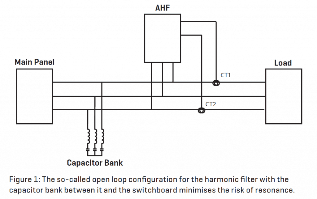
Figure 1 shows the correct way to connect the capacitor bank with the active harmonic filter in open loop configuration so as to minimise the possibility of resonance current destroying the capacitor banks.
Capacitor methods for reducing kVA are subject to voltage variation, the reactance of capacitor Xc being given by: Xc= 1
Therefore capacitor current IC, is given by: Ic= 2πfCV
This voltage dependency can be alleviated by fast-response, solid-state switching, but that works best in circuits with low inductance.
But wait, there’s more
As already stated, revenue meters work on the basis of gross kVA demand.
In a four-wire installation, kVA is given by: V1I1 + V2I2 + V3I2.
The voltage for the phases are with respect to the neutral, and the currents are the phase currents. Unbalanced loads are unfortunately the norm rather than the exception, so that the individual phase kVA, and power factor are different.
In the case of active harmonic filter power factor correction, there is no direct way of compensating for each phase, except for some phase balancing. Obviously, a four-wire filter has to be employed for this purpose.
The problem is in the correction protocol, which – for harmonics and reactive fundamental current – relies on Clarke transformations of three-phase vectors.
This mathematical technique simplifies the correction technique by applying the same corrections in each phase with some correction available for zero sequence current.
Ideally, three individual power factor correction mechanisms should be used in four-wire installations. The power delivered to such an installation is given by: V1I1cosϕ1 + V2I2cosϕ2 + V3I3cosϕ3.
One way of handling this is to employ three single-phase harmonic filters. These are in very short supply.
Another way is to revert to capacitor-based correction but connecting the capacitors in star, and to monitor and correct the power factors in each of the three phases.
Importantly, small capacitor switching steps are required if power factor and/or voltage varies dynamically.
Solar photovoltaic generation
The focus here is on power factor for three-phase installations with ratings of 30kVA or larger. The inclusion of distributed generation in low-voltage (LV) networks is a growing headache for power companies. Lagging power factors in combination with high levels of feed-in will cause voltage regulation.
Technically, the solar photovoltaic (PV) installations are classified as PQ nodes, (P for power, Q for reactive power). Classed as ‘behind the meter’ generators, they are strictly speaking ‘negative loads’ when feeding in.
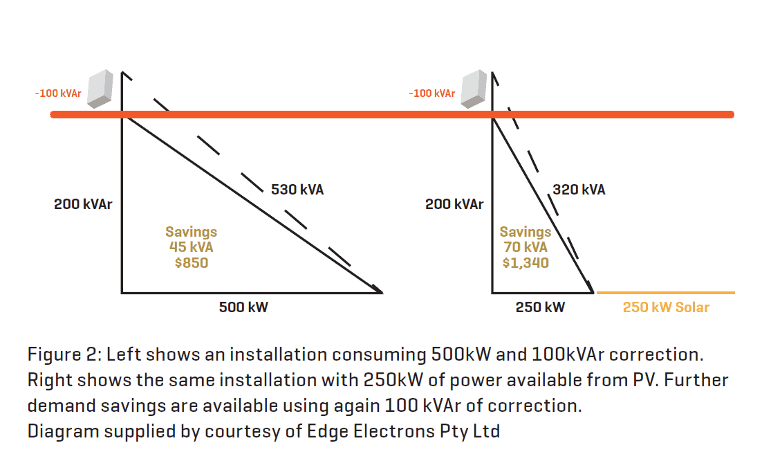
On the other hand, when PV systems are only reducing the power absorbed by the installation power factor, correction is an effective way of reducing kVA demand (see Figure 2).

Now for the crystal ball
Reducing kVA demand will become more important.
Peak load spreading and small levels of voltage reduction at substations are already being employed. Power factor improvement will get more emphasis, with likely requirements that power factors for LV installations follow European norms, ie: 0.98.
Reducing kVA demand also offers business opportunities for electrical contractors in the form of power surveys and installation work.
It demands a bit of marketing, as many electricity consumers are not aware of the matters discussed in this article.
-
ADVERTISEMENT
-
ADVERTISEMENT

