On the tools: Oscilloscopes

Electricians make constant use of basic test equipment, including multimeters, test lights and clamp-on ammeters. Their operation is in various degrees self-evident, and quickly becomes familiar. Oscilloscopes, however, are encumbered by a much steeper learning curve, but if you are willing to put some time into it, the rewards will be significant. In fact modern digital dual-trace triggered oscilloscopes will reveal electrical characteristics of a fluctuating waveform that are invisible to less advanced instruments.
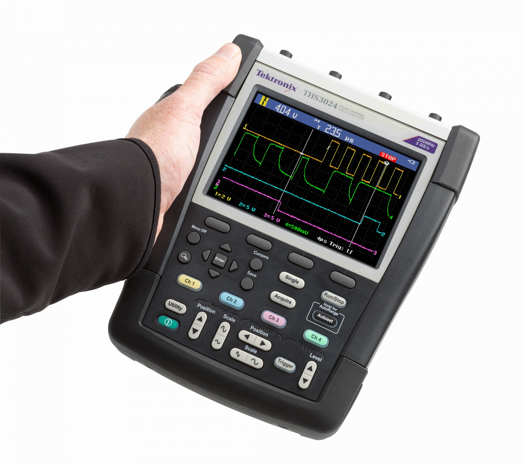
What makes this possible is the graphical display. A cathode-ray tube or flat screen oscilloscope depicts the waveform visually so that an electrician or technician can see the changing waveform including peak-to-peak level, speed and shape of rise-time and decay and intermediate variations and time-dependent properties.
ADVERTISEMENT
To see how this works, we’ll take a look at a typical modern oscilloscope and see how it is hooked up to display the signal.
The screen has two axes. The vertical, or Y-axis, corresponds to the voltage input, as picked up by probes that are touched to the live circuit, or by a coaxial connector on the front panel. The Y-axis is divided into segments that correspond, depending on the setting, with varying voltages. The other axis is the horizontal, or X-axis. It corresponds to time, and it also can be adjusted to different settings, usually a very small fraction of a second.
You could display any type of signal, periodic or irregular, if the X-axis was indefinitely long. But due to limited screen width, this is not possible. When the trace reaches the right-hand side of the screen, it has to jump back to the left-hand side and start over. So that the retrace does not make a confusing line across the screen, it is blanked out just as in a TV. This is done electronically, and is not a problem.
A greater difficulty in early oscilloscope models was that each time the sweep returned to the left side it was liable to start at a different point in the waveform, so the display would jump all over the place and end up a meaningless blur of light.
A technique known as ‘triggering’ met this challenge, and became the basis for oscilloscopes as we know them today. The way it works is that the horizontal deflection circuitry is keyed to a certain point in the waveform, usually the peak. All traces are synchronised and made to coincide, so that a stable image is displayed.
Not long afterwards, the first digital model came out, and since the 1980s it has become dominant. Another important development was dual-trace capability. This means that there are two (sometimes more) inputs so that two separate waveforms can be displayed simultaneously, superimposed, for purposes of comparison.
A modern oscilloscope, with the features mentioned above, is indispensable for solving all kinds of electrical and electronic problems. Schematics for complex equipment, ranging from the colour TV in every home to the synchronous inverter that permits interactive wind power and solar PV systems to tie into the grid, include illustrations of the wave forms present at various points in the circuitry, so you can probe around with the oscilloscope and easily find which stage or component isn’t working.
In industrial facilities, power quality problems are frequent. The presence of harmful spikes or harmonics can be discerned by an oscilloscope so that steps can be taken to correct them.
If a variable speed drive, whereby the RPMs of an AC motor can be controlled by varying the frequency of its power supply, is not functioning properly, oscilloscope readings are called for.
An important specification for any oscilloscope is bandwidth. In digital instruments, this is limited by the sampling rate, which should be ten times the highest frequency you plan to look at. Oscilloscopes with higher frequency capabilities are vastly more expensive, so you need to take a good hard look at the intended application.
The question often arises: Is it possible to convert a TV to an oscilloscope? The answer is yes. Just connect wires to the vertical and horizontal deflection coils and bring them to the outside of the cabinet. But do not attempt this unless you know about the hazardous voltages that linger in TV circuitry long after the set has been turned off and disconnected from the power source. Such a ‘home-brew’ oscilloscope will be an interesting educational project, but is not useful for serious diagnostic work. Similarly, there are software programs available that permit a personal computer to graphically depict the waveform of an electrical input, but this hook-up will not compare to standalone instruments that are available.
On the used market, old oscilloscopes are seen for under $100, but they are for the most part hopelessly out of calibration and lack features that we take for granted today. Parts and service are not available, so this is basically a dead end. The reality is that to purchase the kind of oscilloscope that you would want, the price would be over $1,000.
-
ADVERTISEMENT
-
ADVERTISEMENT

