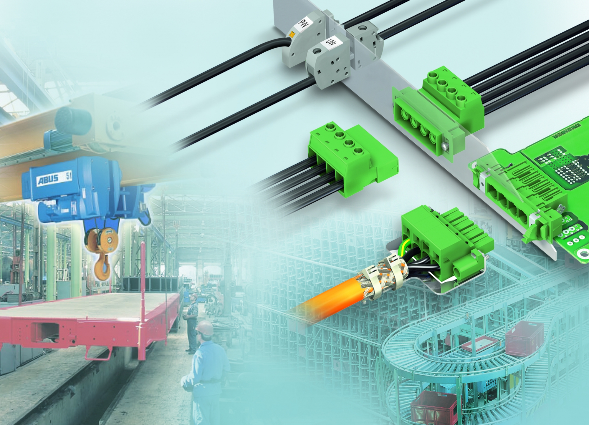
Choosing between pluggable or permanent feed-through

There is a great variety of feed-through terminal blocks on the market, and device manufacturers must know what they want as early as the design process: which connection technology, which connector cross section, which technical features make sense?
If they are looking for solutions for heavy currents and large connector cross sections, they will find that the market has little to offer. Some manufacturers have designed customized solutions out of sheer necessity. However, taking this route often leads to a dead end. Problems can arise quickly, such as maintaining touch protection or insulating the current bar from the device housing.
ADVERTISEMENT
Another problem for device manufacturers is obtaining certification for their devices. If the device is to be used worldwide, IEC 61800-5-1 and UL 1059 certifications are required. Many solutions on the market are unfortunately not adequately certified. offers an extensive range of feed-through terminal blocks for various applications, including high-current applications. The range includes both pluggable feed-through terminal blocks and feed-through terminal blocks for permanent connections. The pluggable feed-through terminal blocks permit quick replacement and are thus service-friendly. In addition, the conductors can be preassembled. However, feed-through terminal blocks for permanent connections are more economical.
Feed-through terminal blocks for permanent connections
Phoenix Contact has been providing these feed-through terminal blocks for almost three decades. Today, the company offers an extensive range of wall feed-through terminal blocks in modern and compact designs. Device manufacturers can choose the connection option to fit the application: fast push-in connectors, conventional screw connectors, or simple bolt connectors (Figure 2). The connection areas range from 0.2 to 150 mm2 and the current-carrying capacity is up to 309 A. The feed-through terminal blocks for permanent connections come in standard and molded designs, either with horizontal or vertical connection directions. The molded version ensures high leakage resistance, even when a small amount of molding compound is used. The product range provides various connection options for space-saving connections in all installation locations. This means that device manufacturers can flexibly select the connection type, direction, and cross section.
The feed-through terminal blocks are installed by snapping them into place in the provided wall cutouts, without the need for tools. Additional mounting options are also available for high mechanical stress conditions: screws or rivets applied from the interior of the housing. If there is not enough interior space, flanges can be snapped onto the outer housing. Utilizing additional mounting options ensures a high level of mechanical stability. The feed-through terminal blocks for permanent connections have a single pole with and without engagement pins on the outer housing. The engagement pins allow the terminal blocks to be snapped together with the required pin count. A terminal without engagement pins provides a flush finish on the end.
In addition to being CE-compliant, the terminal blocks have UL 1059 approval in Use Group C up to 600 V at 309 A. Up to 1000 V at 309 A is obtained in compliance with IEC 60947-7-1. Thus, it is no problem to use these terminal blocks globally.
Pluggable feed—through terminal blocks
Pluggable feed-through terminal blocks consist of a base housing and a plug component. The base housing is either soldered to the circuit board and the plug is plugged in, or a flexible free-hanging cable-to-cable connection is created. The pluggable feed-through terminal blocks have a connection area of between 0.2 and 35mm2 and a current-carrying capacity of up to 125A (Figure 3). Pluggable feed-through terminal blocks also come with both conventional screw connections and quick push-in connections. The terminal blocks can be attached in the housing cutout using screws or with snap-in locking that does not require any tools.
The pluggable terminal blocks have shield models in order to comply with EMC requirements. These models have a metal piece attached to the terminal blocks that prevents electrical interference through a large surface for the shielding cable. The discharge is applied to the metal housing or conducted through the wall for plastic housings. The inverted plug design rounds out the product range. These plugs protect against touching live contacts, thus ensuring that a voltage-carrying housing output is touch-proof.
All pluggable feed—through terminal blocks having a rated current of 16A or higher are equipped with an integrated steel upper spring to provide continuous current-carrying capacity. This prevents bimetallic corrosion, and the contact resistance remains stable even for applications with high temperature fluctuations and vibration. Independent of this, the force required for plugging and unplugging remains comfortable. The derating characteristics can be used to determine which plug connector is most suitable for a particular application. The diagrams show the maximum current rating for the application as a function of ambient temperature, pin count, and conductor cross section.
The pluggable feed-through terminal blocks also have UL approval up to 600V in Use Group C as well as IEC approval up to 1000V. A new type of click—and-lock locking device in the PC 5 terminal series not only saves time, money, and space, but also increases safety. The locking device has received a certificate of conformity from the VDE in compliance with the DIN EN 50155 standard. Using the right terminal blocks makes devices vibration-resistant, allowing them to be used in applications such as railroad technology.
The right solution for every application
Searching for the right application-specific wall feed-through terminal block does not depend solely on the connector cross section and the rated current. The terminal block must always be viewed in its entirety: size, technical features, and certifications must be factored into the decision. When this is done, every device manufacturer can find the optimum wall feed—through.
-
ADVERTISEMENT
-
ADVERTISEMENT

